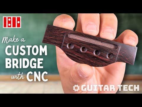
Make a Custom Bridge with CNC
Whether you’re comfortable with 2D CNC work and ready to level up, or you’re simply curious about how modern tools are shaping instrument making, this video offers a practical, real-world look at what it takes to make the jump from flat designs to true 3D parts.
In this episode of Guitar Tech, CNC experts Tom Dalia and Ben Kahler walk us through their complete process of designing and machining a custom ukulele bridge. Along the way, they break down how 3D CAD and CAM software work together, what new considerations come into play when designing in three dimensions, and how learning to use the Z-axis opens up new creative and technical possibilities for designing guitar parts.
Video Transcription
[on-screen graphic reads: StewMac Presents: Guitar Tech]
Tom Dalia: Hey everybody. If you've already dipped your toes into the world of CNC, like engraving logos or cutting pickguards or even cutting slab style bodies, you already know the power of 2D milling. But where things start to get really interesting is taking our first steps into the realm of 3D, which is critical for the Lutherie community.
Ben Kahler: I'm an archtop guitar builder and I used to do everything completely by hand. And even though I love the process, it took a ton of time. Once I brought 3D CNC into my workflow, I was able to push my creative boundaries and consistency to a new level.
Tom Dalia: Adopting CNC is not about replacing craftsmanship. It's about enhancing it. In this video, we're going to take a look at what went into 3D modeling and machining this beautifully carved custom ukulele bridge. It's a great intro into 3D modeling and tool pathing without any crazy curves or surfaces.
And if you do have a little background in CNC, you're still using the same tools, the same machine, and sometimes even the same software. So the learning curve isn't as steep as you think it is. I'm Tom Delia, but most of you probably know me as FrettieMercury (on Instagram).
Ben Kahler: And I'm Ben Kahler of Tikatoo Guitars.
Tom Dalia: Ben and I work as a team to get CAD, CAM, and CNC integrated in guitar builders and repair people's shops all around the world. We work with builders at every stage of the journey. And what we notice time and time again is they get tripped up going from that two axis or two and a half axis movement, AKA the XY coordinates into that dynamic Z axis or 3D milling.
The bridge we're making today is a custom design from StewMac's own Brock Poling. Brock has been making instruments for years, and utilizing two axis milling, but has just recently stepped into the world of 3D. We thought it'd be a real cool idea to show you guys our step-by-step process when we work with folks like Brock.
The first step in any CNC project is coming up with your design. We have a hand-drawn sketch that Brock provided us with.
One of the first things that I like to take in is a lot of these dimensions. Looks like there's quite a few of them. I can see that some of the main things that I need to keep in mind is the width of the bridge and the depth of the bridge. The things that catch my eye are these little inlets that Brock and I discussed the bridge would have as part of its design element.
This would involve creating some flowing curves in the wing surfaces that would leave a little bit of a step across the back of the bridge while still retaining a lot of those modern bridge features that we see on modern day guitars. Like with any project, we need to make sure that we have the right tools for the job. But unfortunately, I don't think StewMac is carrying any computers in their inventory.
Ben Kahler: At least not yet.
Tom Dalia: Well, I guess I'm just going to have to go grab my machine.
The CAD Process
Tom Dalia: So before we get into this, let's take a second to talk about CAD or computer aided design. CAD is a workspace that allows makers to design their part in two or 3D or some combination of the two. VCarve Pro is a popular choice among makers, mainly due to the fact that it's often included in the purchase of machines.
If it's not included in your machine price, you can get it for about $700 and it's so easy to start with. Most people start their journey here.
Ben Kahler: When makers are ready to progress into the realm of three axis machining, they often turn to programs such as Fusion 360, Vectric Aspire, SolidWorks are our personal favorite. Rhinoceros by McNeel. These softwares are the perfect sandboxes to take your designs from ideas and turn them into three-dimensional models ready for machining.
Tom Dalia: So we're going to go ahead and run this sheet through this scanner. We're going to be using the picture function in RhinoCAM, which really likes the JPEG or PNG file type. I'm going to save this to my desktop so it's easily accessible and I can find it in a pinch. In the Rhino screen, I can type picture, and I can go and recall from my desktop.
Now, Rhino is going to ask me if I want to import this as a one-to-one scan, and I'm going to go ahead and do that even though I know that the drawing might not be to the scale that I want it to be. Now, I'm going to be tracing over this scan that we made of Brock's sketch, but it's going to be difficult for my lines to show up over it.
So what I'd like to do is I like to change the opacity of the surface that is created with this photo.I can do this by coming over to this property's object tab and editing the material object transparency. I will usually pull this over so that way when I start drawing over it, my lines really, really stick out.
Another thing that I want to pay attention to is the fact that this is a hand drawn sketch. This might not be square to my XY coordinates, so I'm going to go ahead and draw a four and a quarter inch line across the front edge of this bridge that I can later use to scale the drawing down to as well.
But first, I'm going to make sure that this front edge is definitely aligned with my X coordinate. So we're going to use the rotate command and we're going to utilize the fact that Rhino has an ortho option - and Rhino conveniently allows me to use my shift button to toggle that on and off.
I think now we can go ahead and scale this down so it's the right size that Brock was looking for. I'm going to go ahead and use the regular scale command.
That's going to scale in all three directions rather than just one or two. I'm going to grab that endpoint and go to the other edge of the bridge and pull this back so that way my sketch is aligned to that four and a quarter inch front edge that Brock was looking for. I think we're good to lock this.
So now I don't run the risk of accidentally dragging my drawing out of alignment with what I'm going to be tracing. So I'm going to only work on one half of the bridge and then mirror the rest over and then I can fine tune it. When we are drawing in a CAD software, we want to make sure that our control points are kept at a minimum.
If I have a lot of control points, it's going to introduce a lot of my mistakes, a lot of my human element. I want to rely on the software's ability to draw straight and smooth flowing curve lines rather than my own human shaky hands. So I follow something called the rule of three. And this is the idea that a curved line at its simplest has a start, a point on the curve, and then an end line. If I am drawing a curve and I count to three, then I'm going to get some nice flowing curves that make sense and I'm not going to have any kinks or any clefts.
I've established this wing edge with just a straight line. It's only two points, so that's simple. But when we start getting into these flowing curve lines, this is where I want to pay attention to my point count.
The more points I add in, the less control the software has and the more of my human element is brought into this drawing. We've already scaled this drawing down, so this front edge should be on center with the sketch of the bridge. Brock has also provided us with an overall depth of our bridge from front to back, so I can go ahead and establish that with an inch and a quarter line. As we can see, Brock kind of guesstimated what an inch and a quarter was, but this is what it actually ends up being.
Now I'm ready to use the control point curve option in Rhino, which allows me to start doing flowing curves. I'm going to start at the end point of my line and count to three in my head. Our starting point is at this corner right here, and then I would say that the next curve point is going to be somewhere about here and then there.
I can already start to see that I have a really, really nice flowing line here, but that curve starts to bend back on itself. So what I'm going to do is I'm actually just going to put one more down here and then terminate it. By reducing the amount of control points that I used, this allows me to have this nice flowing curve that is now very easily adjustable by the nudge command, or I can just click and drag it to my taste. I think that's looking pretty good.
So I'm going to go ahead and make a copy of our original drawing and pull it over away from my sketch. But we're missing half of the drawing, so I'm going to select my curves and use the mirror command across my center line. But before I click, I'm going to come down here to hit the record history button, which will allow me to modify our bridge drawing on the left hand side, and you will see the same thing happen to the right hand side.
That's really, really useful when we are drawing something and we want to see how our changes are affecting our original drawing. So now that I've finalized what I want the perimeter of my bridge to look like, I need to go in and add some of the other features like the saddle slot, the bridge pins, and then these unique little inlets that Brock wanted incorporated into the design. I'm just going to go ahead and roughly lay out where these are supposed to be.
One of the neat commands that I can use when it comes to evenly spacing holes like this is the array linear command, which allows me to choose an object and then how many times I want to replicate that object. So in this case, we're doing a ukulele. We only got four strings, sorry, guitar players - but now I can evenly space it out.
Now we can see from the original drawing that we're not quite symmetrical. So I'm going to go ahead and scoot that over just to get a rough idea of where my holes are going to be, and those are going to be decided by the taper of my fretboard. Now the saddle slot, I'm going to go ahead and draw a line where this saddle slot is supposed to be. Just for rough laying this out, getting that saddle slot on there is going to help me visually as I go through the 3D design process. But a line doesn't signify the width of that slot, and Brock is opted to actually use a larger saddle slot than you would typically see on a ukulele. That's for intonation purposes.
In order to get this saddle slot, I can actually just use my favorite command offset. What offset does is it allows me to specify the distance that I want a line to be from another line.
And there's a nifty little option called cap in here. For a saddle slot, the round option is fantastic. Now the problem here is that this saddle slot is going out either direction and the line I initially drew is in the center of the slot.
So I want to make sure that we are going out from that line. So what I'm going to do is I'm going to actually use this both sides option. Now that's a pretty big saddle slot and it's going out by an eighth of an inch, as we can see up here under the distance. Now this saddle slot is supposed to be, get saddle slot width from Tom.
We're shooting for three sixteenths of an inch. Right now, offset is set at an eighth of an inch. So if I were to go ahead with this distance, how big would our saddle slot be, Ben?
Ben Kahler: A quarter inch.
Tom Dalia: That's way too big. So we're going to switch it to being half of three sixteenths. I can type in 1.875 and then divide it by two, and that will give me my desired saddle slot width. Now that I've laid out my saddle slot in my bridge pinholes, that top central line is a great reference point for us to copy one design element over to another while keeping it aligned. So I'm going to grab the intersection there and pull that right over to the midpoint of our other bridge. Now I think that's a little bit too close for the bridge pin holes in the saddle slot, so I'm going to go ahead and do some adjusting.
So I've gone ahead and adjusted my bridge pinholes back a little bit, and I've also reused that offset command to make some ideas where my chamfer's going to go. Now, Brock and I had conversations about a really cool design element that you can see here on the bridge. We have this step down that follows the bullnose of the entire bridge, but the wings themselves have their own individual bullnose that creates this very, very distinct edge.
So I'm going to go ahead and roughly lay out where those are as well, using the same principles that I've been using for the rest of the bridge design. Brock wants them about here, so I'm going to pull that up and over, mirror that over. I do want to pay attention to the distance between my saddle slot and these wings.
You don't want to see any daylight through your saddle slot. That would not be great. I'm going to go ahead and copy this over and then we are ready to rock and roll.
We have a nicely drawn 2D layout of our bridge and we're ready to start making this 3D. All right, so we were very, very careful to keep our point counts down on our 2D sketch, and I think we're about ready to start making this 3D.
I would describe my modeling method as reductive, similar to a sculptor chiseling away material to make their art. And that's how my brain works when I'm taking away material in the digital space. Rhino is capable of viewing a part in multiple perspectives, whether it be the top view, the front view, or the right view. Very similar to the angles that we're getting in this video. But what's interesting is this perspective view, which allows me to view a part in 3D. Now I use a tool called a space mouse from 3D connection that allows me to move parts around in my camera so I can get a really good view of what I'm making.
We're ready to extrude this bridge to start entering the 3D realm. Now, one thing that I need to check is how tall Brock is going to want this bridge to be. Brock asks for this bridge to be a quarter inch, so I'm going to start by extruding my 2D drawing up a quarter of an inch. This gives me a great starting point in reference points that I can now work off of. I do like to switch from the shaded view to the ghosted view, so I could still see design elements underneath my model.
Brock asked for me to incorporate the radius of his fingerboard into the top of the bridge. So I'm going to go ahead and establish that radius on the front of my bridge, just using a simple circle. Now, one of the things that I find is very useful in Rhino is that I can switch between views to access different axes.
We're going to add in that 16 degree radius in the front view because that allows me to hit my Z axis, but I'm going to multiply it by two. Now, I was never good in math class, so I'm going to use the calculator and we're going to make it 16 times two. Now, if I wanted to, I could start doing that reductive modeling using commands like wire cut to go ahead and cut this radius into this bridge. Now it's going the wrong direction.
So I'm going to switch my direction to the Y and anything that is highlighted is going to be cut away. Now the problem is that I don't want all that cutaway. I want the top part cut away. So I'm going to click on it to invert it and press enter and now I have this radius. Now Brock asked me for a specific width of this height for this surface right here, and I'm not going to be able to get that with this radius.
So I'm going to need to make some modifications to it in order to get the right height. So I'm going to take some time to get that right and then we'll be right back. So I've gone ahead and modified this arch so that it terminates at a 30 second all the way around the bridge, which will now allow me to cut into this bridge and leave the desired lip that we were looking for. That looks pretty good. So I'm ready to keep rolling ahead.
Now, this bridge has a radius that goes from the front of the bridge towards the back. So I'm going to want to go ahead and incorporate that element into the bridge now as well. I don't like how many control points are on this front arc. If I were to type rebuild, I can see that I have a point count of 46, which is way more than I need.
We said that an arch at its simplest is going to be three points, but because we have that radius, I'm probably going to use a four or a five, so that way I can modify it so it terminates down at that 30 second mark. So I'm going to go ahead and change the point count to five in my degree, which affects the weight of the control points to a two. That gives me a much more simplified shape that I can now work with to modify it. Now we can move on to that bull nose that is going to create the slope off of the back of the bridge.
Without getting too deep into the concept of tangency, the idea is that I want this arch to come up in such a way that it flattens out as it gets towards the top. Now, if we remember, our control points, we want three, a start, an end, and a point on the arc.
Well, if I were to go in and cut this arch into this bridge, the second control point is going to have to be at the top of that radius. So I know that I'm going to need to be there, but how do I decide where I need to start my arc? We already decided that when we decided that our bridge is going to be a 32nd all the way around. So I'm just going to actually copy up my footprint to establish that 32nd edge all the way around, and that gives me my starting point for my bull nose. A lot of the time what I like to do is I like to establish vertical lines that will allow my helpers to reference something.
So I can use that now as an intersecting point between that vertical line and the back of my bridge.
I can go up to the front edge of my bridge, but that's going to produce a straight line. What I really need is that three point to create that arc. Rebuild will allow me to create three control points rather than two that I could then take that control point and stick it on the top of that arch. By projecting that point up, I now get my nice bull nose all the way across.
I'm going to need a flat surface in order for my bridge to have that nice flat across the back. So what I'm going to do is I'm going to create a line across the back of my bridge from where I terminated my bull nose, and then I'm going to take these wing lines and extend them to that point and then trim them again. Again, a very reductive way of modeling things. By doing it this way, I can assure that everything is going to line up perfectly.
The CAD software is only as good as you are as an operator. So if you draw something sloppy, your part's going to be sloppy. And now we have the makings of our first surface. So now we can start to visualize what our surface is going to look like. We've built out a framework that's going to allow us to stretch a surface through these curves that we made. The command that I like to use to do this is one of two commands, either network surface or Sweep2.
Sweep2 is my favorite command in Rhino, and it's what I do probably 80% of my sculpting in. Basically, Sweep2 works like a train where you have two rails, and the train is going to follow that rail. I'm going to go ahead and try Sweep2. My first rail is the back of the bridge. My second rail is the front of the bridge, and then we have our curves in between, or as Rhino calls it, our sweep shapes. When I press enter, it's going to give me a visual of what that surface is going to look like, and I'd say that that looks pretty dang good. I'm going to press okay, and there is our surface.
Now, this surface is not a part of our model, so I'm going to use this surface to cut away some of this material, and there are a few different ways that I can do this. The first way is using something called boolean difference. Now, boolean difference is based on the direction of a surface. Rhino has an active surface that it uses, and I can see that using the DIR command, which is short for direction.
And we can see that the surface is facing up, and that's our active surface. I'm going to want to flip that, and if I go up to the top here, hit the flip button, it'll go down. Let's see if Boolean's going to work. Oh, how beautiful. It worked like a charm.
Now, one of the important things to note is it's produced these lines that are going across my surface, and these are what we call ISO curves. Iso curves can be your friend, and they also can be really annoying, especially when you're in other views. So when I switch to another view, it looks like they're lines that I never drew. So I can actually go into my properties tab and turn them off, and now I can see it as a regular surface without anything that I didn't draw. That helps with a lot of confusion.
Now, we have a great start for the rest of this bridge. We have the geometry that Brock is looking for, but we also wanted to incorporate in these wings that add this nice step to the bridge. We already have laid out where we want our wings to terminate in 2D, but they're not following the geometry of this surface that I just made. So we're going to use a command called Project, and Project works like shadow puppets.
When you have light and you have an object in front of that light, it is going to project a shadow. Project in rhino works the same way, but with curves and surfaces. So if I use Project, I can take a curve and conform it to a surface that I already have there. Then all I need to do is modify these endpoints to pull down to where I want it to terminate to create that effect that Brock is looking for in his bridge.
Now all I need to do is create a second surface similar to my bullnose that's going to produce the result that I'm looking for. I'm going to draw a line straight out from where this curve terminates, and then I'm going to utilize this front edge of this bridge as my trimming point. The same way that I created the surface on the front, I'm going to do on this wing surface. Using my Sweep2 command, I'll go from a flat to a round and then use my sweep surfaces here, and that creates me a beautiful surface that's going to produce that step that Brock is looking for.
Following this idea of reductive modeling, I'm going to need to create another surface that's going to allow me to cut away material from this bridge. We're missing a bit of geometry here, but I think I can use some of the tools in my software to fill in the gaps that I'm missing without having to go draw it out.
Instead of using the extrude curve command, I'm going to use extrude SRF, which allows me to make a 3D model from a 3D surface, which is pretty useful in some cases. This is going to let me create some material that I can cut away, leaving that nice tapered step down where I need it. The height of this surface doesn't matter because it's going to get deleted anyways, so I just want to make sure that it intersects with my model some amount. Now, we're going to go back to that boolean difference and see if I can utilize it to cut away the material to create this wing. Now that is perfect.
Unfortunately, I didn't mirror my surface when I did the boolean, so I'm just going to have to mirror it over and do the same thing to the other side, but since I've already created this surface, this shouldn't be too big of a deal.
And now we have a beautifully modeled bridge with a few more details that we can cut in. So one of the interesting issues that we ran into with a bridge like this is actually these chamfers around the bridge pinholes. Now, in most cases, StewMac makes a great tool that indexes right off of your bridge pinhole and does this chamfer, but because this surface is going back over it, you're going to find that your chamfer will be deeper on the front of the bridge than the back.
So we've gone ahead and actually modeled this chamfer into our surfaces when we did this model, which is a bit advanced for this video. However, StewMac does sell another great tool, which is this little reamer that you can use with just your fingers. Just don't cut yourself. That allows you to actually come in and chamfer it at an angle without losing any more material on the front edge than you need to.
Now, the last things that I need to address in my model are the bridge pin holes in the saddle slot. I typically don't like to put holes through things and I like to avoid slots. And the reason for that being actually has to do with our cam software, which we'll talk a little bit down the road. Putting these holes in will make the bit want to fall in and might cause some sort of deflection that I'm not looking for, but I'm going to go ahead and do it just so that we can see what that looks like. I'm going to go ahead and again, use my extrude command to create some surfaces that I can cut away from my bridge.
Now, rather than only going one direction, I'm going to have this go both directions. So we have some big looking tubes here that I'm going to use to cut away from my bridge, and now I have my bridge pinholes.
In my saddle slot, I'm going to go ahead and extrude it, turn off my both sides, and then hit a boolean difference again to cut away that surface from my model. Now we have a perfectly modeled bridge ready to mill it. Now, one of the things that I want you guys to note is that I've left these surfaces for my wings in place.
Now, one of my other techniques when I go and I model things is I like to leave the components that I use to cut it in place because it helps in our cam process down the road. So I don't recommend going through taking everything that we just drew and deleting it, but instead utilizing our layers in the bottom right hand corner. So I've gone ahead and put all of my 2D modeling into a trace layer. So now when I go to my 3D bridge and I hit this little light bulb, all of that drawing, except save these guys, has gone away.
And I can go ahead and add those back into that trace layer just so that way I'm not getting confused. If I ever need to go back and change something, rather than starting from zero, I have those frameworks to recreate those surfaces or edit them if need be.
The CAM Process
Tom Dalia: Now that we have a good 3D model, we're ready to exit the world of CAD and enter the world of CAM. We love to use a software called RhinoCAM, which is a convenient plugin for Rhino that allows us to save our tool pads and our 3D model in one convenient file.
Ben Khaler: CAM stands for computer aided machining. These softwares translate your visual design into tool paths or a numerical language the CNC machine can understand to then mill the design. For CNCs being such amazingly complex pieces of equipment, they all run off of simple USB drives containing these G codes.
Tom Dalia: So let's go ahead and launch RhinoCAM and I'll walk you through our process. So now that I have my parts situated on this jig that Ben has made, I'm ready to start laying out my tool pad. So I'm going to go ahead and open up RhinoCAM, which looks like this. Now the RhinoCAM menu is deceivingly simple.
We have two sections where we have our machining browser, which shows us what the tool path is actually doing, and then also a menu that's showing us the tools that we're using. I'm going to start by walking us through radiusing the bottom of the bridge. Now, while we typically say that acoustic instruments have a flat top, that's not actually true. They actually have a radius top, which is typically a spherical radius rather than a cylindrical radius. By radiusing the top of our instrument, we're actually adding more structural stability without having to add weight.
Now, what does this have to do with the bridge? Well, if we're going to be gluing this bridge to the top of our instrument, we want to make sure that that reciprocal radius is built into the bottom. So that's going to be the first step in my cam process. So first I need to mill that radius into the bottom of my bridge, and I do so using a tool path called parallel finishing and RhinoCAM.
The way parallel finishing works in rhino cam is I specify an area that I want it to mill in, and then the software is going to look for a surface in that area and its features to add it into my mill. So to do this, we've created a 3D surface in a 2D area that we want the machine to mill in that's going to put that radius in. Using that quarter inch bond mill, it's going to look like this when we simulate it.
We are going to rough a lot of this material away, but being as close to our stock size as possible when we go to actually mill this is going to prevent any sort of deflection or discrepancies in our mill. All right, cool. Now that that radius has been built into the bottom of our bridge, we're also going to add in some indexing holes on the bottom of the bridge so we can locate it on the jig that been conveniently already made for us.
Now, not only are these holes useful for indexing on our jig, but down the road, when it's time to glue this bridge to our top, we can actually make a jig with these reciprocal holes so we don't have to use our bridge pinholes as an indexing hole for gluing our bridge on.
This prevents us from having any sort of squeeze out coming up through those bridge pinholes because no one likes cleaning squeeze out anyways.
Now that we have that block radiused and those pinholes milled, we're ready to flip this over onto the reciprocal side of the jig that has our radius built into it. From this point, we're able to start roughing in some of these features using a regular flattened mill. So we have a program here that's going to flatten the face of our bridge to get everything evened out. We're using a quarter inch bit to do this, which takes off material.
Then we have a final pass that's going to take off the last little bit of material and give us a nice flat surface. Then we're ready to start roughing in this bridge. RhinoCAM has an algorithm called horizontal roughing or a tool path that goes in and looks at the features of a 3D model and calculates out how far it should mill, leaving enough material for us to get a nice surface without taking off too much.
So we're able to specify how closely we want it to follow that model through something called stock. So the stock parameter is something that we can use to have it follow a line right on the line or leave a little bit or even take away a little bit. Right now, we have it set to have a stock of 35 thou, which means when we measure this, it's going to be 35 thou larger than our final product. This tool path is done with an eighth inch flat end mill and looks something like this.
What's cool about this feature is I don't have to decide any of this. I just tell the program where I want it to cut and it uses my 3D model to decide where it's going to put tool paths to remove some of that material. We don't want to be digging through a quarter inch of material with these bits because they are so small.
I mean, this bridge is smaller than the size of my palm. So the bits that we're going to need to use in order to do this are going to have to be pretty small as well. And this is something that we consider when we actually start milling things. The size of our bit is going to be decided by the size of the features that we want to be defined. After we've gone and roughed in the model, we're going to switch over to a quarter inch ball end mill to use that parallel finishing program again.
There's a few more features that we're going to need to mill in this. Now we're still using the same square area that we want it to cut, but the parallel finishing is paying attention to our surfaces and it's going to move along our Z axis, our X axis and our Y axis to achieve that three axis milling.
That looks something like this. Since we've gone in and horizontal roughed this, we have a whole lot less material that we need to take away.
So after the features of the bridge have been milled in with that quarter inch ball end mill, we can notice that some of our features are not very defined, so we're going to go back in with an eighth inch flat end mill to bring in those features. Now you might be asking yourself, how are you using a quarter inch flat end mill instead of a ball end mill.
Ben and I have milled a lot of classical bridges and classical bridges have a lot of radius surfaces that also meet with a flat surface. That 90 degree angle can be very, very difficult for a ball end mill to define a feature. So RhinoCAM has the capability of compensating where the tool path is going to go to allow us to use certain sides of a flat end mill to define 3D geometry.
We found this to be extremely useful when you have 3D geometry that's curved and flowing meeting with those 90 degree angles. So we decided to go ahead and use that eighth inch flat end mill to define those very, very sharp steps that Brock wanted incorporated into his bridge. That looks something like this. Now that the 3D milling is out of the way, we can get back into familiar territory with our 2D milling. So if you're a pro at 2D milling, you're ready for this.
We're going to go ahead and use something called axis pocketing to clear out material for the saddle slot of our bridge. This does not have to be 3D geometry. We can very simply just draw our 2D saddle slot and tell the program how deep we want it to cut. So don't feel as though you need to go in and model every single part of the bridge, because in some cases it can be defined with what you already know.
We're using a eighth inch flat end mill to rough out the material for this saddle slot. What we like to do when we're milling things is we like to use an access profiling tool path to hog out material sometimes at a faster speed and with a deeper step over. Step over is the amount that a bit is going to step over when it's going and cutting geometry.
So if I have a pocket that I need to cut and I'm using an eighth inch bit, that pocket is going to take multiple passes around and how much of the bit is entering my material is going to be defined by the step over parameter in my CAM software. After we've access pocketed a saddle slot, we do like to go back over it again with access profiling. What access profiling does is it just traces the line dependent of the bit that you're using and it just allows us to really bring in that slot the rest of the way.
Another useful part of access profiling is when you use a larger bit to clear out material and then coming back over with a smaller bit to bring in those finer details. CNCs hate corners. We're using a round bit in a square hole. So the larger the bit that you have, the more rounded your corners are going to be. The smaller your bit is, the sharper those corners are going to be. So depending on how good you are with the chisel, might decide what size bit you want to use when you're doing your access profiling. That program looks like this.
Now that we have our saddle slot defined, we can come in and profile our bridge. Using that same access profiling, we are going to go and cut out the actual shape of our bridge. This is why back earlier on in the design process, I wanted to make sure that I had a nice 2D model in order to follow those lines without any sort of lumps or bumps or discrepancies.
Again, you will see that we are doing a larger pass that's oversized utilizing the stock feature, and then we're coming back over in deeper passes, taking off less material, but really defining those corners. Those two programs look like this. And then last but not least, we've gone through and we've pocketed our bridge pinhole.
Now, a helpful tip when it comes to pocketing bridge pinholes, especially when you decide to mill using a vacuum work holding fixture, is that you don't want to put holes all the way through the bridge. If you go and do that, then you're most likely going to break your vacuum seal and your bridge is going to go flying off your machine. So now that all my tool pads are set, I'm going to go ahead and post this G code over onto a USB drive. The default post processor that we use is for a different machine that Ben has in his shop.
Today we're going to be using a ShopBot CNC machine, so I'm going to switch this over to the ShopBot post processor. Now I want to make sure that I'm naming it something that I can distinguish when I'm over there on the computer. So don't name it a bunch of random characters, maybe name it by the steps that you're going to be doing. So I'm going to call this Bridge Radiusing for the first process, and then I'm going to go ahead and post the other one as Brock Bridge Top.
RhinoCAM will actually output the G code, and this is actually the language that our CNC machine is actually going to run. If you've ever played Battleships, it's identical to that classic game. We're just using different coordinates and different commands at different speeds. In an industrial setting, most CNC operators actually know how to read this and can adjust it on the shop floor.
I think we're ready to bring this over to the CNC machine and get this cutting.
The CNC and Workholding
Ben Kahler: So now we're going to take our USB that has our G code on it. And we're going to get it pre-processing while we get our machine ready to cut our bridge. Today we're going to be working with a ShopBot Desktop MaxATC, which has a feature that every machinist like me would love to have, an ATC or automatic tool changer.
Tom Dalia: An automatic tool changer is an essential tool for shops looking to have a more hands-off experience with their CNC. This machine is capable of changing the tools as it's working the job, so that leaves us with more time to go do other projects.
Ben Kahler: Now one of the bigger challenges of milling in 3D is making sure that your stock stays fixed to your table. Methods such as double stick tape and toggle clamps are great in the pinch, but not for parts that you're going to repeat over and over again. For this project though, we're going to show you our preferred method, which is to create a jig such as this one.
This is made specifically for Brock Poling out of three quarter inch bridge plywood. It has radius surfaces for the bottom of Brock's jigs, steel pins that locate the bridge, acetall pins that locate on both top and back. And we also took the liberty of having our ShopBot mill holes for threaded inserts in the table to accept this. So now we're going to go ahead and affix our dig to the table.
Now it's time to attach our blank to our jig.
I've taken the time to sand this side perfectly flat. So now I'm going to take double stick tape, put it on the back side, deal off the backer from this bridge. Bump it up against my pins here, make sure that it's pressed down as best as I can. We're ready to machine.
Router Bit Selection
Ben Kahler: Now that we have our bridge solidly on our jig, we're going to talk about the four bits that we're going to use for this entire project.
Tom Dalia: It's absolutely critical to make sure we're choosing the right bit for the right job before cutting into our precious tonewood. Bits are a lot like brushes that an artist would use. They come in a lot of different shapes and sizes for different jobs. We're going to start our process by putting that radius into the bottom of our bridge so that way it better glues to our top. Now, because this isn't a very detailed area, there's not any features that we're actually going to have to be milling into this besides that radius. We've opted to go for this quarter inch ball-end mill.
Ben Kahler: Ball-end mills have round ends. Because of this, they can cut at angles that aren't perpendicular to the workpiece and leave a smooth finish. Due to the design of the tip, they're not able to easily make plunge cuts, so they're often used with square end mills to complete a job.
Tom Dalia: But for the job that we're using for, it's the right tool. Then we're switching over to a 50 thou flat end mill.
Ben Kahler: Square end mills are the most versatile. They have one to four spiral flutes that end in a flat bottom, which makes it perfect for something like making a sharp corner between the bottom and walls of a pocket. They can do roughing work, cut outlines, cut slots, and their spiral flutes help remove chips as they work.
Tom Dalia: Not only will these holes index on the pins that we've included on our jig, but we also can utilize them when the time comes to glue our bridge to our top. After that, there's going to be a lot of extra material that's going to be a bit more difficult for our detail tools to come through and get those fine details that we're looking for. So we've opted to actually use this quarter inch compression cutter.
Compression cutters are interesting in that they cut up and down. So they're sharp in just about every direction, but they're great for hogging away material at fast speeds. Now, one of the interesting features of Brock's bridge are these really, really nice step-ups, and we wanted those to be very sharp and we wanted them to taper off into basically nothing. And unfortunately, our ball end mill is not capable of doing that because it's going to leave that radius.
So we've actually opted to use an eighth-inch upcut bit. This will allow us to go in and keep our wall 90 degrees to the spindle while still retaining the detail and roundness of that wing. After we've gone and removed all of that material, we're going to go back over with a finishing pass with our quarter inch ball end mill. So obviously we've preloaded our rack with the tools that we're going to be using, but let's take some time to talk about the anatomy of a tool holder and how to load it.
Our tool holder is made up of three main components, starting with the body. The body is typically conical in shape with a draw stud at the end of it. This stud allows the spindle to actually pull this holder into the spindle pneumatically. So that means that your machine is going to be hooked up to some sort of air supply, as you can see back here.
Then we have our collets. Our collets come in different sizes, not only to hold different size tools, but also to go into different size tool holders and different size spindles. It's critical to make sure that you are getting the right size collet for your spindle. Last but not least, we have our lock ring. These are generally threaded on the inside to accept the threads on the body of our holder. It's really important to make sure that we are not cross-threading these threads as we're putting them together, and we also don't need to over tighten these.
I've ruined so many tool holders just by thinking I needed to really put my whole body into tightening that up, and that's not always the best case. Tight enough is good enough. I'm going to start by putting my quarter inch bit into this quarter inch collet. I'm mindful of the flutes of the bit.
There's something called a length of cut, which is the actual length of the cutting part of the bit.
And I really don't want that going underneath my collet because it's going to pull my wood chips into that collet and potentially cause a jam. Then it's really a pain to get these to come apart, and you could actually potentially ruin your collets. After I have my bit in my collet, I'm going to go ahead and insert it loosely into the tool holder, but I need to use some other tools to tighten it down, and I don't have the hands to do that.
So ShopBot has conveniently designed their machine to make this job easier. We're going to go ahead and take this wrench and insert it into this magnetic part of the machine that will actually hold my tool holder while I work on getting it tightened down.
Now I have a free hand to do all of the other jobs that I need to be doing, and then I'm going to tighten down on this, but I'm not going to really put everything into it. I'm just going to get it tight enough. Now, this is ready to go onto our tool rack and we're ready to start cutting. One of the scary concepts of CNC machining related to bit selection is speeds and feeds, which at its simplest is the speed that the spindle is moving through a cut at any given motion, whether it's approaching our blank, it's moving through a cut, or it's retracting.
Speeds and Feeds
Ben Kahler: In the metal working industry, speeds and feeds are much more defined because we have much more consistent material than wood to work with. But in woodworking, we use chipload calculators to get us within the ballpark of where we need to be. Chip load is calculated by feed rate divided by spindle speed times the number of flutes a given bit has. Then we compare our result to a chip load chart like this one.
The chip load chart is a guide as to where we should start when setting our speeds and feeds. It tells you how much a given material you can or should remove in order to get a good finish on your workpiece.
Tom Dalia: But have no fear. I'll explain what all that mumbo jumbo means. Basically, every machine has different capabilities, whether it be in the spindle or in the speed that the gantry can move. So if your spindle is not able to move as fast as you like it to, you can always adjust the speed of the gantry to account for that, which makes our chip load calculator a sliding scale.
You can plug in numbers to make sure that you're getting within that range that the chip load chart is telling us we need to be at. But sometimes we find that we need to make adjustments even based on the unique piece we're cutting.
Ben Kahler: Yeah, the other day I got some front boards from my buddy, Aaron, and I noticed that I broke a lot more bits and figured Ebony than I do in regular Ebony.
Tom Dalia: This is something that experience is going to be your best teacher. So you need to get in there, cut some wood, break some bits, and experiment. You need to find what is best for you, your machine, and the specific material that you happen to be cutting.
Zero Out Coordinates
Tom Dalia: All right. It looks like the machine has the G code pre-processed. Our speeds and feeds are set, the tools are on the rack and ready to go. Our part is ready to be cut, but before we can hit that go button, we need to zero our X, Y, and Z coordinates on the machine so it knows where it's at.
Ben Kahler: Now the CNC utilizes a coordinate system that tells the Gantry that holds a spindle where it's at at any given time.
Tom Dalia: See, the coordinates changing in real time. The CNC has soft limit switches built into the chassis that are physical locations that tell the machine not to go past this point. If you think about it, it's like the global XY, but where does our XY zero come in? Well, the XY zero is something that we are able to choose. We like to use that global XY zero as our set XY zero.
Then we go into our CAD software and locate our tooling and our part off of the true XY of our drawing and then sync the true XY of our drawing up with the global XY of the machine given to us by those limit switches.
Ben Kahler: Now that we have our X and Y homes, the Desktop MaxATC comes with this conductive probe that works to zero the Z by creating electrical contact between the tool and the plate.
Tom Dalia: We prefer to put the probe on the top of our work holding. And the reason for that is we're able to set the bottom of our part as our Z zero. Now, as we talked about, everything works by coordinates. So by putting the probe on top of this jig, we're able to reference it over and over again.
I see a lot of newbies wanting to zero off of our actual stock, but the problem with that is we're going to mill away that material that the probe was once sitting on. So if we needed to go back and remill something, we can't. It's already been milled away. So let's get the probe connected to our machine. Clip this alligator clip right to my bit. Ben is going to go ahead and put it on a good part of the jig. We want to make sure that we're working off of the flat sections of the jig.
Now I'm ready to head over to the computer and start jogging my machine into position. Now that we're located along our X axis, I'm going to move us along our Y axis into position over the probe. That looks right. Under our cuts feature, there is an option to zero our tool off of our plate, which is called a plate offset.
So it looks like tool number one is all zeroed. From that motion, the machine now knows how much of that bit is exposed from the collet, and it also knows how far up this jig is from our spoil board, but we're not done yet. The machine still has no idea how long the tools are on our tool rack, so there's a probe on that side that the machine will automatically zero off of.
The Cut
Tom Dalia: All right, folks, the moment we've all been waiting for, let's hit, go, and let this machine get to work.
Ben Kahler: There we go! Wow, that looks great.
Tom Dalia: Oh man, let me see that thing. Wow. Our edges are so nicely defined on this on the perimeter. Those facets came out great. I'm really, really glad that we switched to using that flat end mill instead of a ball in mill there just to get that nice and defined. Going that extra mile really made the difference in this, but one of the things that we can't avoid when we're doing CNC milling is mill marks.
Here we can see our mill marks, which are these lines that are running parallel to the front end of our bridge. What actually produces them is compression from our tool, similar to when you use a drill bit on an archtop guitar to set the depth. And just to compare it, this bottom bridge is one that we've already sanded the mill marks out of.
Final Sanding
Ben Kahler: Now it's come time to final sand our bridge. One tip that I have that a lot of people might not be aware of is using a piece of curfing as a sanding call to sand complex parts such as this bridge. So what I like to do with this is take a piece that's a good size for the job I'm going to be doing, and then I kind of like to pre bend this. So it has a little bit of a backing here.
Once I have that, I'll take a piece of sticky-back 220 and I'm going to put my piece of curfing down on that and I'll just trim off what I don't need. So the first thing I'm going to tackle when sanding this bridge is getting into these corners or the transition between the center of the bridge and the wings. We left a little bit of stock there just so that we wouldn't get any kind of weird transitional mark on the top of the bridge.
Now that I have those corners done, I'm going to tackle the wings. This sanding caul is doing a great job at getting into all the fine areas of these wings. The last part I'll tackle is the center of the bridge. I really love that definition. Me too. It's looking pretty good.
So if you want to leave your bridge with more of a matte finish, you can leave it at 220, but if you're going after that really sleek polish, you can take it up the grits from 320, 400, 600 steel wool, and even a little bit of finishing oil to really give it that nice polish.
Tom Dalia: That finishing oil really makes it pop. There's one thing we know for sure. This bridge is going to look amazing on the Torrified Sitka ukulelele top Brock has waiting for this thing.
Ben Kahler: And the great thing is if he's happy with the design on this, he can replicate it perfectly. He's got the CNC, he's got the jig, he's got the files to do it.
Tom Dalia: We hope that this video gives you a better sense of what's possible in your shop taking those big steps into 3D design.
Ben Kahler: And with this knowledge, you now have the power to take on other cool projects such as fretboards and necks.
Tom Dalia: If you're looking for or more content like today's video, have no fear. I teach this every weekend live on Zoom in my online CAD and CAM design courses. All the information and links will be in the description below.
Ben Kahler: And don't forget to comment below with any questions you might have. We'll do our absolute best to follow up and get them answered for you.
Tom Dalia: Thanks for watching. Thanks to StewMac for having us, and we'll see you guys next time.


