Understanding Guitar Wiring, Part 2: What is a potentiometer, how does it work?
At StewMac, we’re passionate about guitars, and that includes understanding the tiny but mighty components that make them sing. One of the most crucial, yet often overlooked, parts of your guitar's electronics is the potentiometer (or “pot” for short). Whether you're upgrading your pickups or just want to get a deeper understanding of your guitar’s wiring, knowing how potentiometers work and how to choose the right one is essential.
What is a Potentiometer?
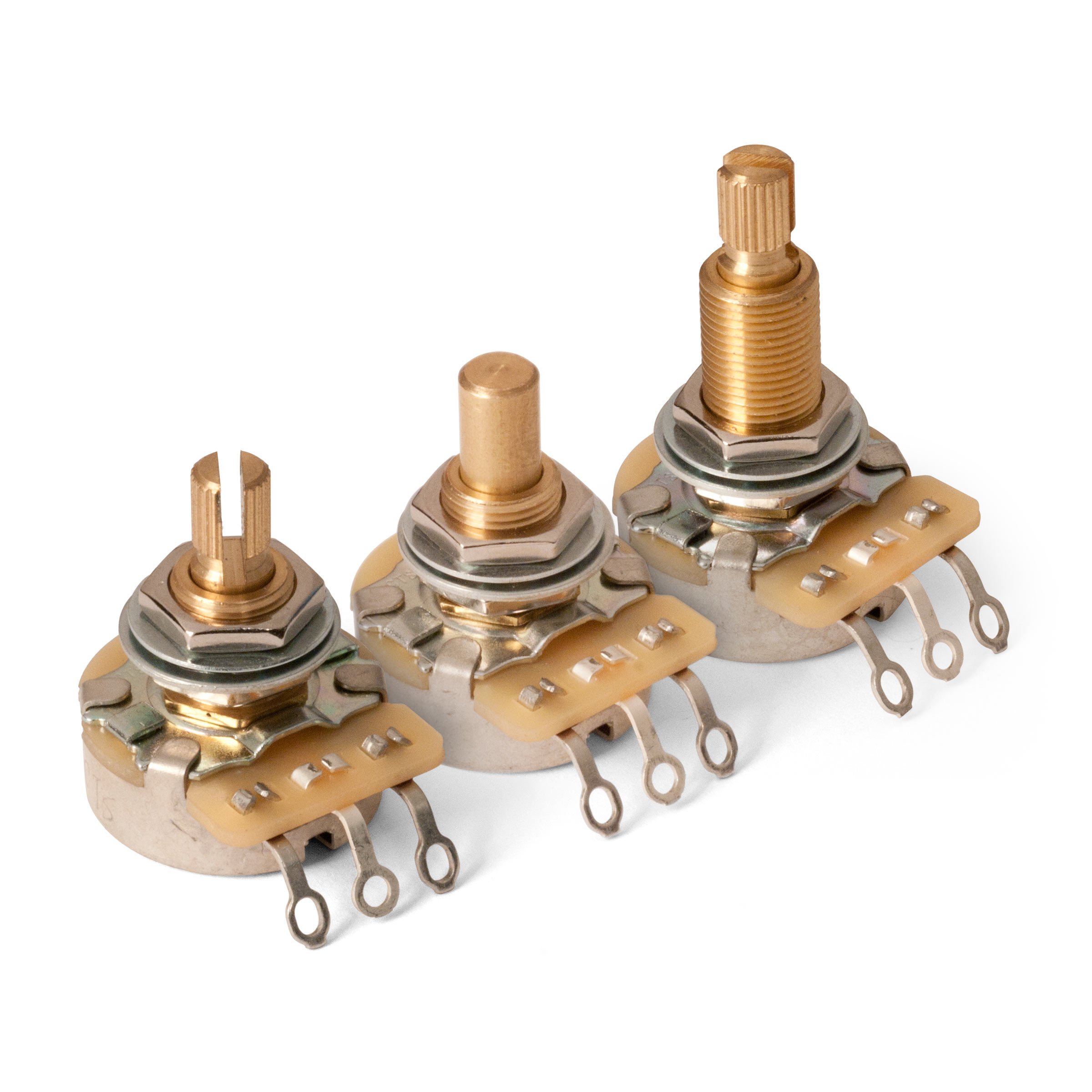
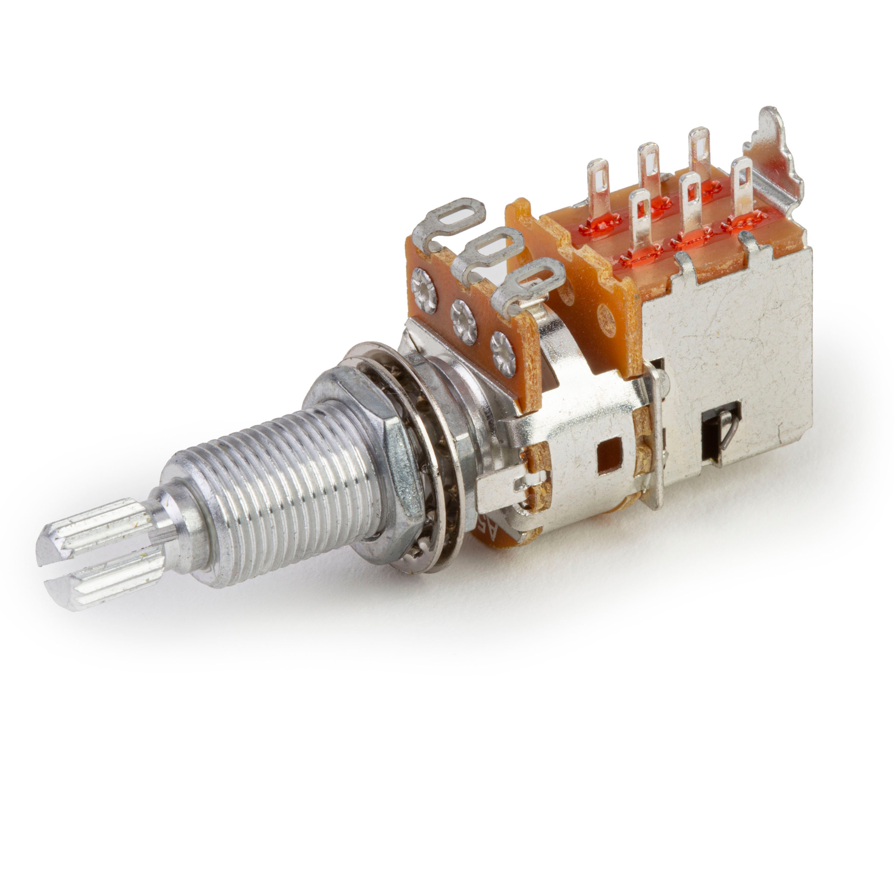
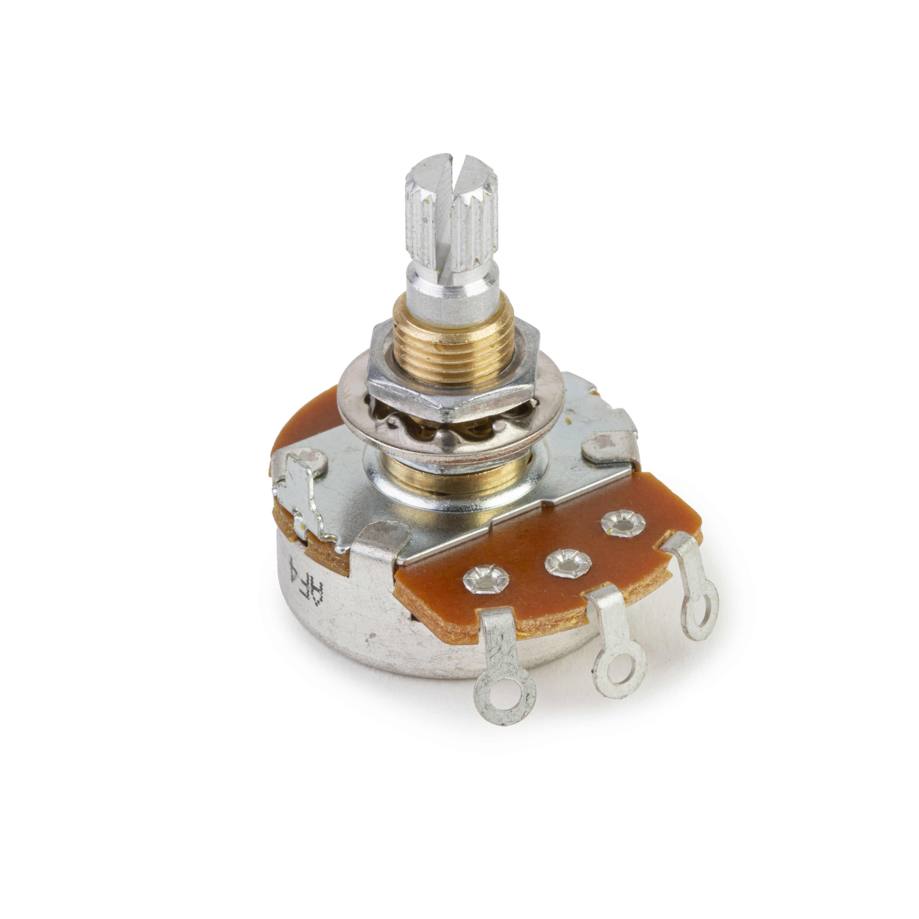
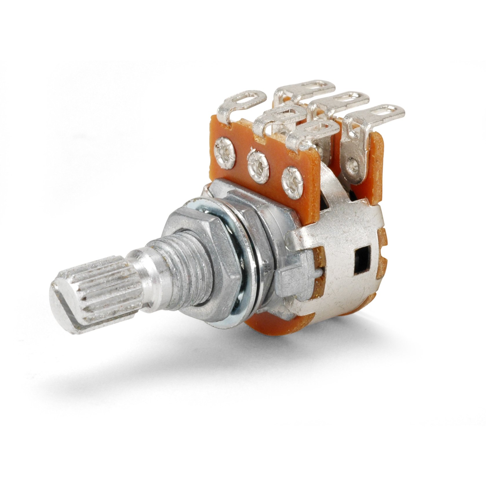
In guitar electronics, a potentiometer (“pot”) is a 3‑terminal adjustable resistor (voltage divider); when wired on two lugs it behaves like a simple variable resistor. Inside, a rotating wiper sweeps a resistive track, changing the resistance between the wiper and each end lug—this varies how much pickup signal goes to output vs ground. Wiper position sets the voltage split: in a volume circuit it controls how much pickup voltage reaches the output jack; in a tone circuit (with a capacitor to ground) it sets how much high end is bled off.
A pot has three lugs: the two outer lugs tie to the ends of the resistive element (carbon, conductive polymer, or similar material), while the center lug is the wiper. Turn the knob and the wiper sweeps the track, varying the resistance “distance” between hot and ground. In a volume circuit this sets how much pickup voltage reaches the output jack; in a tone circuit—where the wiper works with a capacitor to ground—it forms a low-pass filter that bleeds high frequencies to ground and lets the lows pass to your amplifier.
Types of Potentiometers
Not all pots feel or respond the same. Taper (how resistance changes as you turn—we’ll get into this) affects how volume/tone “comes on.” Below are the types of potentiometers you’ll actually run into in guitar and related electronics:
- Linear Potentiometers: Resistance changes evenly with rotation (50% turn ≈ 50% resistance). Some builders like linear for tone because the sweep feels broader; others still use audio taper. Usage is preference, not a hard rule. Marked “B” on most U.S. guitar pots (some imports reverse letters).
- Logarithmic (Audio) Potentiometers: Resistance change accelerates toward one end, matching human loudness perception so volume feels smooth. Widely used for guitar volume and also popular for tone in many factory wirings. Marked “A” on most U.S./CTS‑style pots (note: some import makers flip A/B).
- Multi-Turn Potentiometers: Require several full turns for full travel—great for precision trim settings in electronics, but rarely used as front‑panel guitar knobs. You might see them inside onboard active preamps or studio gear, not typical passive tone circuits.
-
Trimmer Potentiometers: Small board‑mount adjusters set with a screwdriver—used to calibrate gain, bias, EQ centers, or blend in pedals, rack gear, and active onboard electronics. Seldom exposed on a guitar’s top.
Types of Potentiometer Tapers Explained
You’ll hear techs talk about a pot’s “taper” when describing how it changes value as you turn the shaft. Taper is the relationship between rotation (mechanical position) and the electrical division of the pot’s total resistance (and thus output voltage). In guitar work you’ll mostly encounter two common types of tapers (others exist—reverse audio, S‑curves, no‑load, etc.):
- Linear Taper: Resistance changes roughly in direct proportion to rotation (50% turn ≈ 50% of total resistance). Because our ears hear loudness logarithmically, linear pots make volume seem to “jump” early; some builders still like them for tone because the sweep feels spread out. Usually marked “B” on U.S./CTS pots (some imports flip the letters).
- Logarithmic (Audio) Taper: Resistance change is skewed so the first part of the turn makes a smaller electrical change—matching human loudness perception for a smoother volume roll‑off. Most guitars spec audio taper for volume (and often for tone). Marked “A” on most U.S./CTS pots; some import brands reverse A/B, so check. If you want an even, gradual drop in volume, choose audio taper.
Potentiometer vs. Rheostat
You might also hear potentiometers referred to as rheostats in some contexts, but these are two different things. The terms get swapped a lot, but they describe how a variable resistor is used. A “potentiometer” is the 3‑lug part we use as a voltage divider; a “rheostat” is that same (or similar) part used on two connections as a simple variable series resistor—often in higher‑current/power circuits.
- Potentiometer: Three terminals (two ends + wiper). Wired across signal and ground it acts as a voltage divider—how guitar volume pots are typically wired. Tone pots often use a pot but wire it as a variable resistor feeding a cap (rheostat‑style).
- Rheostat: A variable resistor wired on wiper + one end lug in series with a load to vary current/voltage drop. Many power rheostats are wirewound and rated for higher currents. Any standard pot can be used “as a rheostat” by using two lugs (often tie the unused lug to the wiper for reliability).
In guitars you’ll almost always use standard potentiometers rather than rheostats; true high‑power rheostats are uncommon. Still, understanding rheostat wiring helps when modding pedals, amps, or special onboard circuits.
Choosing the Right Potentiometer for Your Guitar
In most passive electric guitars you’ll see 250kΩ and 500kΩ pots (total resistance between the two outer lugs). Other values exist (300k, 1M, 25k for active systems), but these two are the standards.
- 500k Pots: Common with humbuckers and darker pickups. The higher resistance loads the pickup less, so you keep more high‑end detail—helpful for balancing the naturally fuller humbucker voice.
- 250k Pots: Standard on many single‑coil guitars (Strat/Tele style). Lower resistance loads the pickup more, bleeding a bit of treble to ground and softening the naturally bright single‑coil tone.
When choosing a potentiometer for your guitar, match pot value to pickup voicing and your tone goals: higher value = brighter / more open; lower value = warmer / smoother. Mix values (or use resistors) in HSS/HSH guitars to balance pickups. Actual pots vary ±10–20%, so measured value matters too.
Testing Potentiometers with a Multimeter
Testing a pot is quick. For best accuracy, disconnect it (or lift at least one lug) so other components don’t skew readings. Here’s how:
- Set your meter to resistance (Ω) and auto‑range (or pick the next range above the pot’s rated value).
- Measure across the two outer lugs to read the pot’s total resistance (should be near its rating—e.g., ~250kΩ, ~500kΩ—regardless of knob position). Big deviations = bad pot / wrong value.
- Now move one probe to the center (wiper) lug and leave the other on one outer lug. Rotate the shaft: resistance should sweep smoothly from ~0Ω to near the full value (curve shape depends on taper: linear vs audio). Repeat wiper‑to‑other‑end to confirm full travel.
If the reading jumps, goes open (OL), dead‑spots, or never reaches near the rated value, the track or wiper is worn/dirty—clean or replace the pot. Small residual resistance at the extremes is normal.
Play with Confidence
Now that you understand the basics of potentiometers, including how they work, how to choose the right type for your guitar, and how to test them, you're ready to make your guitar’s electronics truly sing. Whether you're replacing old pots or experimenting with new ones, keep this knowledge in your back pocket to help you get the most out of your instrument.
At StewMac, we’re here to provide you with the best luthier tools and expert guidance so you can keep your guitar playing at its finest. Enjoy tinkering with your setup, and remember—we’ve got your back every step of the way.
More in This Series
Part One: How a magnetic pickup works
Part Two: What is a potentiometer and how does it work?
Part Three: How is a volume pot wired?
Part Four: What is a capacitor and how does it work?
Part Five: Selector Switches
Part Six: Mini toggle switch basics and push-pull pot basics
Part Seven: Output Jacks
Part Eight: Grounding and Shielding
Part Nine: Understanding impedance and impedance matching
Part Ten: Wiring Glossary
Part Eleven: Sample Diagrams


