Understanding Guitar Wiring, Part 3: How is a volume pot wired?
How is a volume pot wired
In order to control the volume of an electric guitar, the signal is directed through a pot. When wired as a volume control, the pot allows you to vary the amount of electrical current flowing through it. By sending part of the signal to ground, a volume pot controls the amount of electrical signal the amplifier receives. If the sweeper, which is usually the output of a volume control, is connected to the lug that is grounded (zero on the volume knob), then there will be no output. If the sweeper is connected to the other end of the resistive strip (10 on the volume knob), then the guitar would be at its maximum volume level.
The value of the volume pot used is determined by the guitar's pickup(s) and the preference of the player or builder. Generally, 250K pots are used with single-coil pickups, and 500K pots are used with humbuckers. A higher value pot can produce a brighter tone, while lower values can fatten the tone by attenuating some of the high-end frequencies. This is because that there is always a certain amount of signal going to ground, even at full volume (10 on the knob). High frequencies are the first to go to ground; therefore a lower value pot will allow more of these frequencies to pass to ground, rather than out to the amp as a part of the guitar's signal. Experiment with different value pots to see which ones work best for you.
Typical wiring
Diagram #4 shows a typical guitar pot. The "hot" output (sweeper; lug 2) pans between the "hot" input (lug 3) and ground (lug 1).
Reversed (Jazz Bass) wiring for independent control of volume
If a guitar has two or more volume controls that are wired in the traditional manner (a Les Paul for example), an interesting thing occurs when the selector switch is in the middle position. The volume control for the neck or bridge pickup will turn down the whole guitar—not just its respective pickup. Yet, on a Fender Jazz bass, which doesn't have a selector switch, two volume controls somehow allow you to turn the pickups up or down independently, without affecting the output of the other. How is this possible?
The reason for this is simple. Since the volume controls are in parallel and the output of the volume pots is the sweeper, when either of the controls is turned down (applying signal to ground) the sum output (what the output jack and amp "see") is "short-circuited" to ground. To resolve this problem, simply swap the input to lug 2 and the output to lug 3.
This means that the output jack or the amp never really see or are shorted directly to ground—the pickup is shorted to ground instead. The overall tone of the instrument is not affected, since the DC resistance of the resistive strip that attenuates the high end is still present. Refer to diagram #5 for an example of this wiring.
Blend controls
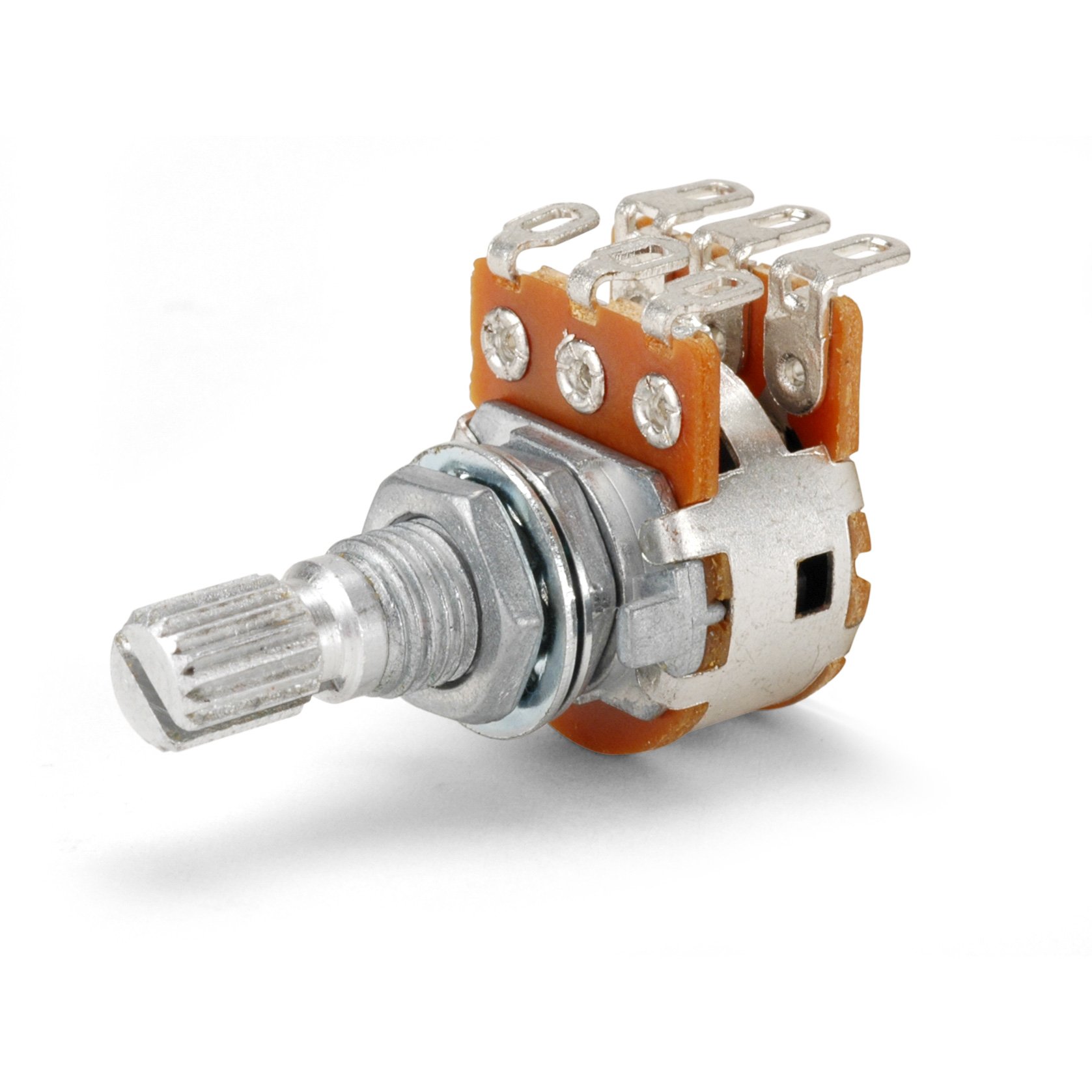
These specialty controls combine two audio taper pots that are ganged together and controlled by a single knob shaft. As the shaft is rotated it moves the sweeper in both pots simultaneously. Blend controls typically have a "center detent," which lets the player know that the pot's in the center of its rotation. At this point both signals are at 100%. Blend pots are the same as "balance" controls found in home or car stereos. They pan the output level from left to right.
To further understand a blend pot, we need to analyze what is happening as the knob is rotated. Starting at zero, with the pot shaft rotated fully counterclockwise, one channel (we'll call it "A") or pot is at 100% output and the other channel/pot ("B") is at 0%. As we rotate the knob clockwise to 2.5, "A" remains at 100% and "B" has gradually increased to roughly 50%. When we reach 5 on the knob (halfway through the blend pot's rotation), both "A" and "B" are at 100%. As we continue to 7.5, "A" has now decreased to 50% and "B" now remains at 100%. When the pot reaches full clockwise rotation—10 on the knob—"A" is now at 0% and "B" is still at 100%. Refer to diagram #6 below for a graphical representation. Since these are audio-taper blend controls, the taper is logarithmic.
More in This Series
Part One: How a magnetic pickup works
Part Two: What is a potentiometer and how does it work?
Part Three: How is a volume pot wired?
Part Four: What is a capacitor and how does it work?
Part Five: Selector Switches
Part Six: Mini toggle switch basics and push-pull pot basics
Part Seven: Output Jacks
Part Eight: Grounding and Shielding
Part Nine: Understanding impedance and impedance matching
Part Ten: Wiring Glossary
Part Eleven: Sample Diagrams


