Episode 3: INSTALLING CAPS, TRANSISTORS+LEADS
V-PEDALEP3
If you've ever wanted to build your own pedal kit but didn't know where to start, this replay of our live build-along series has all the tips you need.
In this 4-part series we show you step-by-step how to build our Interval Fuzz pedal. Even if you're a complete beginner, don't worry! We go over everything from unboxing, to choosing the right soldering iron, to making every connection. We also give tips on painting your pedal.
Video Transcription
[on-screen text reads: Live Build-Along Interval Fuz Pedal Kit Part 3: 8pm Eastern, Wed. September 2, 2020]
Pete: Hi folks. We're live here at StewMac continuing our live pedal build video series. Tonight is episode three, and we're going to continue to turn this box of parts into this pedal. So last week, we went through populating our board, started with a clear board and added or soldered all of the resistors and diodes into place, and ended up with something like that. And then this week we're going to continue to populate the board, adding all of the capacitors and transistors tonight. And I think Tommy was getting ready over there with another demo. Tommy, you about ready?
Tommy: Yeah, I'm ready, Pete.
Pete: All right, take it away.
Tommy: So tonight, I've got strat style guitar, single coil pickups. The previous episodes we've done humbuckers, which give you a nice saturated fuzz tone in addition to that octave up that we talk about. And then we try to P90 last week of another fatter sound, a little more output. Tonight we're going to hear it with single coils, which give you maybe a little bit less saturation. Those previous episodes, we also paired it with a drive pedal and a fuzz, a distortion pedal. This week we're going to pair it with another modulation effect, a phaser pedal, so you can see what it sounds like when it's not just stacked with another drive pedal.
So for here we've got our clean tone with the interval fuzz pedal. And without the fuzz pedal. And now with the phaser pedal. And now with both pedals on. So again, you can see it really does stack well with a lot of other effects. And even with single coil pickups, you can get some pretty cool harmonic distortion going on, just depending on how you play it.
Pete: All right. Sounding great. So let's hop right into it. I think we ended with step four last week. So starting on step five tonight, on page nine in the instructions. And for all of you that this is your first video with us. Welcome. If you'd like, we have both episode one and two of the live series available on our YouTube channel, so you can review those. Everyone who is returning, welcome back.
Step 5: Install 6 capacitors
Tommy: So I think I'm ready to go. I got my soldering iron turned on, heating up. Like Pete said, we're in step five now. We're going to install six capacitors. Capacitors are found in almost every audio circuit. They control voltage, they filter frequencies, and they're just a vital component in small electronics products like this, or projects like this. So that phaser pedal that I have, I built that from a kit as well, and that has just a ton of the little capacitors in it, as well as resistors and diodes.
Pete: And how exactly does a capacitor work, Tommy?
100pF capacitor
Tommy: Well, in this kit, there are two kinds of capacitors that you find in most audio circuits. You have electrolytic capacitor, like the first one we're going to do, which is a 100 UF cap, and that is an electrolytic capacitor. All caps essentially block DC voltage and pass AC voltage. Electrolytic capacitors work a little bit differently. They're often used to filter the hum out of a DC circuit. So again, this is our 100 microfarad capacitor, and it goes in this slot here.
If you can see that Rachel, on the board, it's labeled for polarity. Polarity meaning positive and negative voltage. Each poll like the poles of a magnet, are going to be electrically charged positive or negative. For electrolytic capacitors, it is vital that you get this polarity correct. For a kit like this, it has it labeled on the board with a plus for positive. The body of the component itself is labeled. Generally, the band will be your negative side, and also with nearly all electrolytic capacitors, one lead coming out of the body will be longer than the other, and that is your positive lead. So there's a bunch of different markings and ways for you to tell which way is the correct way. Very important that you get that right.
Pete: And there's also another indicator on the board as well, with the actual pilot.
Tommy: Yeah. So yeah, good call Pete. The eyelet itself for the positive lead is square instead of a ring like all your other components, eyelet for your components. So again, this one, you don't really need to mess with the leads. You can just drop that in, get it as close down to the board as you can and pull those leads apart on the other side of the board, just the same way we've been doing this whole time. Is that a good shot, Rachel?
Rachel: That's perfect.
Tommy: Cool. So again, that's going to hold it in place and also help have a good structural connection inside your solder joint.
Pete: Now you mentioned that that was an electrolytic capacitor. What does that mean, electrolytic?
Tommy: Electrolytic is the actual stuff inside it. In most capacitors like this next one, which is our 100 picofarad capacitor, in most capacitors like this, there's going to be two plates and what's called a dielectric in between that stops those plates from touching each other, which is essentially why in most capacitors DC current can't pass through it. There's no direct connection. You don't really need to understand how it all works,. But essentially what it is in an electrolytic capacitor, is there's only one plate and a thin oxide piece that allows the signal to pass in one direction only.
If you apply the voltage in the wrong way, it's going to burn up that little film plate and destroy the electrolytic inside it. It's going to smell really bad, it might smoke or explode. And if you've ever let the smoke out of electrolytic cap, you know exactly what I'm talking about. So again, 100 picofarad is our next capacitor.
Rachel: Oh, you going to shove that one.
Tommy: Sure. So this may look a little different, it just depends the supplier. Sometimes these are rounded and have a little polyester coating. These have a little bit fatter body and a little bit different marking, but this is our 100 picofarad cap.
Pete: Okay. Yeah.
Tommy: So we're going to drop that in this top spot.
Pete: So regardless of the outer appearance of it's still the same kind of capacitor?
Tommy: It's the same kind, it's still a film cap and it's still the right value. Now, before I solder that in, I'm just going to make sure that I can get this other component in next to it, because again, it is a bit bigger on the body. So let's see here. I'm going to pull that out a little bit just to leave myself a little more space next to it.
47nF capacitors
And that next component is your 47 nanofarad capacitor. Let me just see here. There we go. So I can see that I've got the leads for both of those caps coming through my board.
I'm not going to have an issue with this build. And again, if you have a larger component like that, you may need to just work with it, to create the space you need to get the other components in there. So what I'm going to do is still bend those legs back a little bit, to hold that in place there. Cool. We're not going to have an issue with the rest, as they're all pretty small profile components. So we've got three of those 47 nanofarad caps and they're marked on the top. I don't know if you can see in a close up on that, Rachel, but we do have a graphic as well. They do have a pretty good marking there. Pretty clear, especially with a magnifier like our fancy OptiVISOR. You can get at stewmac.com. I know a lot... I saw some comments where people were clamoring after the OptiVISOR.
Pete: Yeah, after last week's episode. So I saw in that closeup, there's some type printed on that. Can you explain how capacitors are kind of coded, or what that's indicating?
Tommy: So 47n is your 47 nanofarad. Then a 100 is your 100 volt rating. Capacitors are rated for voltage as well as capacitance. Capacitance is measured in farads named after a hero of mine. Michael Faraday, brilliant British physicists scientist, he discovered electromagnetics among a host of other just groundbreaking amazing things. But the farad rating is the capacitance measured in farads and then there's a voltage rating as well, which is more like a guideline. If you exceed a hundred volts, it's not necessarily going to blow up, but the manufacturer isn't guaranteeing it to be safe. If you go too far above the voltage rating, it'll melt that dielectric in between the plates and short it out and probably let the smoke out.
100nF capacitor
So for our last cap, we've got a 100 nanofarad, and that just goes in between those two 47 nanofarad caps.
Pete: So I'm noticing that the leads on these film capacitors are the same length, unlike the electrolytic capacitor.
Tommy: Right. So they're not polarized. I didn't say that in the beginning and I apologize for that. These small film caps are not polarized. You can install them in any orientation you want. I like to just make sure all the writing is facing the same way. Makes it easier down the road, you need to swap something out or troubleshoot. It's really easy to visually identify those caps by the print and if they're all facing the same way, like I have them here, it just makes it easier, so you don't have to flip your work around.
Solder in the capacitors
So I've got all my caps loaded. I'm going to go ahead and flip my board over. I'm going to start with this electrolytic, just because those caps or those leads are so long. My irons nice and hot. And again, I've got a bunch of soldering tips in that first episode. Some other good ones in the second episode.
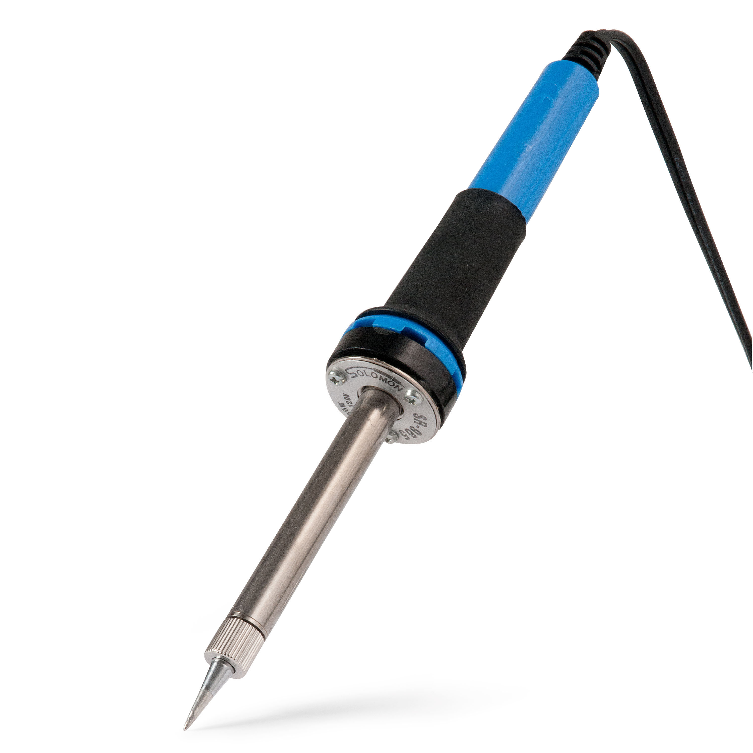
But again, you want to have a nice hot iron tip, you want to have a clean tip. Damp sponge is my personal favorite. We've also got this nice Stay Hot Tip Cleaner, which will help avoid any heat drops, help you work a little bit more quickly and you really need to tin your tip properly. Just a small amount of solder on there and kind of roll it around, wipe it off, make sure you have just a perfectly shiny tip to conduct all that heat properly. So now I'm just going to start with that electrolytic. Again, you can do them in any order you want. I like to get in there and get those big leads out of the way, just so it's easier to access everything else.
Pete: Tommy, we got a question here from someone in the audience from BC Rich 581, looking for a little clarification. They say, "So the cap retains energy but doesn't drain steadily like a battery, instead it dumps all its stored to energy in one shot."
Tommy: That is a pretty good explanation. There's a lot of different ways people like to use analogies to describe electricity. The way I like to think about it is you're dealing with DC, which is constant voltage and you're dealing with AC. Those are all present pretty much everywhere in your signal. And the capacitor has a maximum charge it can hold and the AC signal makes those flip. So that's, how the filtering happens, and that's how those charges are dropped and recharged based on the frequency of your AC signal.
So if you are playing a low frequency signal, those wavelengths of your AC current are going to be longer, and it'll take longer for it to charge and recharge, discharge and recharge. High frequency will pass easier, because it's changing so quickly that they don't have as long of a discharge and recharge period, if that makes sense.
Pete: Yeah. All right.
Tommy: That's kind of a lot of information. Hopefully that makes sense. There's a lot of really good resources on how caps work, both on our site and other sites regarding electronics. So I'm just going bottom to top this time. I cleaned that tip there. All right. And just these last three caps up here. So you can see that solder isn't wanting to flow into the joint, it's just bawling up. That's a good sign that my tip is not properly cleaned and tinned. So I'm going to go ahead and do that again. Again, you want the solder to flow to the joint, not to the component, or to the soldering iron. There we go. That's what I'd like to see.
Pete: We had a comment on episode two from Duncan Hill regarding the stickers. When Tommy put the sticker on his pedal enclosure last week, we mentioned that it comes with not only the decal for the front, but also for the input and output jack and the DC power jack. Duncan asked "the sticker decals are nice. Do the kits that have volume gain tone pots, et cetera, have sticker decals for the control knobs with names and new numerical markings for the control pots?" They do have labels for what each control pot does. They don't include numerical values around the dial.
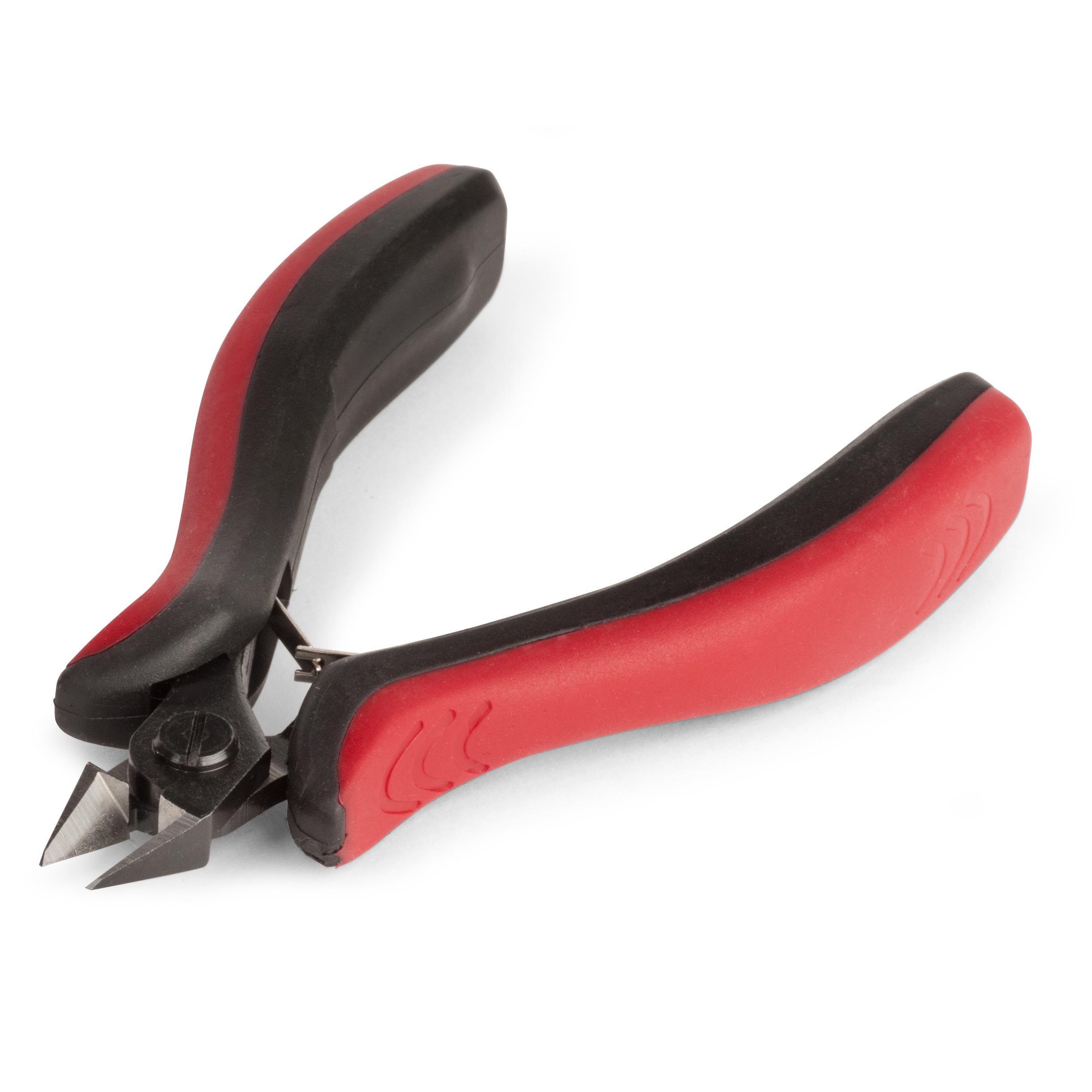
Tommy: Which there's a lot of pedals out there, that don't have any numerical values either. It can get cluttered pretty quick, especially if there's more than say, one or two knobs. Luckily we've got no knobs. So I'm going to clip all these excess leads. I inspected my work with my magnifiers. It all looks pretty good and I think we're going to be good to go on all of those. So again, I like to just keep all these little leads as trimmed as I can. Makes your work look tidier and it also helps avoid any kinds of risk of short circuits or anything like that.
You don't need to go crazy getting them all the way down flush to the joint. It's pretty easy to damage a joint with a pair of clippers like this. So I recommend you just take off what you feel is appropriate. Nothing too crazy. If you can see that Rachel?
Rachel: Oh yeah.
Tommy: Okay. Yeah. So I have leads sticking out all over the place, but none of them are long enough to touch any of the other joints. They're certainly not long enough that they're going to touch the chassis or case of the pedal.
Pete: All right. So that's step five. Those are all the capacitors, right?
Step 6: Install 3 transistors
Tommy: Yeah, that's all of our capacitors. You can see we're really getting our components pretty much loaded up. We've just got, I believe, just three more components on the main circuit board. So we're on step six and we're going to install three transistors. So we're going to start with our 2N5089 transistors. These are NPN transistors. Transistors are also polarized essentially. There's three pins referred to as an emitter, a base, and a collector. And those can either be positive or negative, if you want to think about it like that.
2N5089 transistors
Then the base is generally what your guitar signal is feeding into, to affect how the signal is amplified, or clipped by those other two leads. So we're going to start with those 2N5089 transistors. They're in the instructions. They're also labeled here on the board, so I've got that top one. And for those legs, I just pulled these out just a little bit to get them started.
It'll get tight on its own once you get closer, because where they go into the body is a tighter spread than on the circuit board. It's kind of by design, so it'll just basically hold itself in there. I still give these just a little courtesy tug over here just to make sure they're not going to go anywhere. And again, it's not all the way flushed down to the board. It doesn't need to be. Just as close as you can get it, you don't want to force it.
Pete: Tommy, since these are polarized, how do you know the correct orientation? How do you know which lead goes into which?
Tommy: Yeah, that's a great question, Pete. So you can see on the component it has a flat side and a rounded side. Can you see that Rachel?
Rachel: Just a second. And yep, there it is.
Tommy: Perfect. So the flat side is also notated on the PC board and in the instructions. So if you just pay attention to that outline, you'll be fine. And now transistors, you're probably not going to burn them up the way you would a capacitor, but it just wouldn't work properly. So again, I just pulled those leads out just a tad, got that in the right location and I'm just guiding that through as best I can, down to where it doesn't want to go anymore and that's fine. There we go.
2N3906 transistor
And now I'm just going to add that last 2N3906 transistor. Now it came with a little piece of cardboard on the leads. Just pull that right off of there. And we've got essentially the same thing, but this one has its legs already kinked for me, so that's convenient. It'll just fit right in there. Again, it's got the same markings on the face and it's still got the same flat side. You can see that Rachel, basically looks exactly the same as those other ones, aside from some of the writing and the legs on this one are kinked. Some manufacturers do that for certain transistors and some don't.
Rachel: I can see the legs on that one again.
Tommy: You can see they're already kinked out into the proper spacing.
Pete: So Tommy, what are the transistors being used for in this pedal?
Tommy: In this pedal and in most pedal kits, they're used to amplify your signal. There's no tubes obviously in this circuit to amplify a signal. So the transistor was invented to be able to make things smaller and still get the same kind of voltage amplification, that was formally before the invention of the transistor unavailable outside of large transformers or tubes or what have you.
So these components in particular are kind of what enabled the guitar pedal to be a reasonable thing. Before smaller transistors, the only guitar effects were big giant things that you'd have to sit on top of your amplifier powered with tubes. They are heavy and temperamental, to say the least.
Pete: All right.
Tommy: So we're good here. I'm going to go ahead and solder these transistors.
Pete: So while you're doing that, we've got another question from the audience here. From Scout they ask, "Will the voltage from your fingers damage these components?"
Tommy: No. Most of these components are rated for 50 volts at least. Maybe that electrolytic is 25. If you have more than 25 volts in your fingers, you should contact a doctor. So in all seriousness, static can cause problems. I'm working on this nice StewMac Bench Pad. If I was walking around in wool socks in the driest weather and things like that, I might be a little bit concerned about static. But for most people in a normal working environment, you shouldn't have any serious concerns about that type of thing.
If you are concerned about static, they have static work pads that you can buy that are designed specifically... Wear a little wristband and it attaches and it's essentially makes sure that you can't create any kind of static spark that might cause a problem, but I've never had a customer contact us about a damaged pedal kit due to the voltage in their hands or static electricity.
Pete: Yeah. All right.
Tommy: So I'm going to clip those leads and folks, we are done adding the components to our PC board. So give yourselves a pat on the back.
Pete: Step six, complete.
Tommy: Step six is done.
Pete: All right, so moving right along to step seven here, We're going to be installing the lead wires, right?
Step 7: Install 8 lead wires
Tommy: Yeah. So what we're going to do is stop and prep all of our lead wires at once just to make it more efficient. This is how I like to do it. If you're quick with a wire stripper, you can do it as you go, but we're going to go kind of meticulous and do it the right way. So I don't have my ruler today, so we're just going to eyeball the links. But if you do have a ruler, that can be pretty handy as well.
Pete: I think we might have a ruler here in the studio.
Tommy: It's nice to be in a professional studio with all the tools.
Susan: Let's see. Let's see what we got.
Pete: Well, while Susan is looking-
Tommy: I got calipers over here with a ruler on it.
Susan: There we go.
Tommy: There we go.
Susan: Do you mean action gauge?
Pete: I've actually used that before.
Tommy: It is four inches, right? No, it's three and a half inches. I need four inches. I'm going to use this Calipers. So this caliper has measurements right on the body of it too. Again, not important that they're exact, it has just a little bit more wire than you're going to actually need. If you follow the guidelines, none of your jumpers are going to be too short, which is the most important part. It's much better to be an inch too long than an eighth of an inch too short. So again, this kit comes with 24 inches of pre-bond wire, 24 gauge.
Pre-bond wire is tinned, meaning you don't really have to tin it, but I'm going to show you how to do that anyway, just in case you're working with other wire you've got around the house. And also because not all pedal kits come with pre-tinned wire, we do want this to be helpful no matter what project you're working on. So it says cut the wire into eight 2 inch sections in two 4 inch sections. I'm going to cut the four inch sections first just for simplicity.
That is not four. There we go. I don't know if you can see that Rachel, but-
Rachel: I think that's a pretty good shot.
Tommy: Measuring four inches is not the most complicated part of this kit. So I'm sure you guys can all take care of that. And you can either just match this to your other one, or just measure. Since we've got this here, I'm just going to measure. And again, it doesn't need to be exactly four. They don't need to be exactly the same, but those need to be long enough, because those are going to reach all the way from your input and output jacks, all the way down to the switch. So they do need to be longer than the other ones. Four inches is good. It leaves you a little bit of slack, service loop is what we call that.
And so the rest of these are just two inches. I'm just going to go through and cut those and put them off just separate from my four inch pieces. Are there any more questions from the audience, Pete, or anything else that you were thinking of?
Pete: No. Right now, it doesn't look like we've got anymore questions from the audience. I was wondering, we've been referring to the wires coming off of the components as leads, but now we're cutting and then soldering the leads onto the board. What is the difference really here?
Tommy: Yeah, lead is just a term for the... People call these jumpers. People call them conductors, they call them wires, they call them all sorts of things. Leave comments if you've got some fun verbiage for your leads. The main thing is that these are forming electrical connections between points on the board and points elsewhere. A lot of times they're referred to as jumpers as well, jumping from one area to another. It's not super techy, but it is just kind of what we call them.
Pete: All right. And so you mentioned that this wire is pre-tinned, sort of in the same vein there. We've been saying that you have to tin your solder tip, keep it tinned. How is that different than tinning a wire?
Tommy: Tinning a wire is adding solder to it to allow to make a quicker and more reliable connection with the intended location, whether that's on a jack or on a eyelet or wherever else. Pre-tinned wire just makes everything simpler. It also adds a little bit more rigidity to the wire itself, which is nice when you're trying to keep things in place. What I'm going to show you though is something that can happen even with pre-tinned wire, it can come kind of unraveled.
And if that happens, a good idea is to tin it so it's nice and solid again. Now it takes a bit of finagling to get it to break up, since it is soldered altogether. I'm going to just rub on it with that there. So there we go. So if it starts to come unwound and fray a little bit, you're going to want to tin it. So you can see it's a bunch of little conductors and if you can get a close up on that, Rachel.
Rachel: Let's see here. There you go.
Tommy: So you can see instead of a nice solid strand clump together, we've got a kind of nasty looking frayed end. That can happen, ton of different reasons. If the wire was crunched or something, it's not the end of the world. So you can see, I just twisted it back together and then I'm going to tin it just to make it a nice solid conductor again. Again, this was spare, so we're not going to use this in our kit, but I'm just going to wedge it in this little board holder here, if you can see that still.
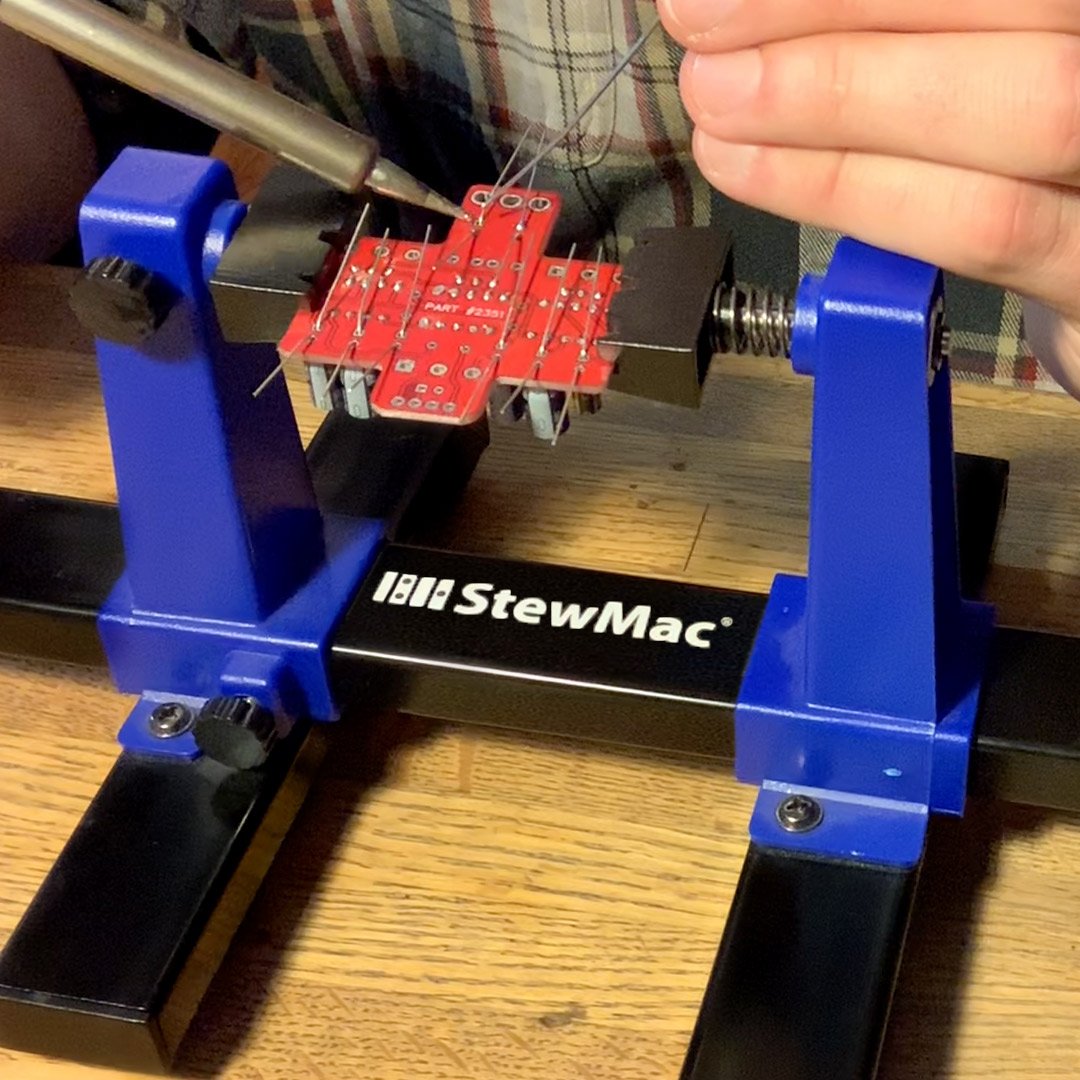
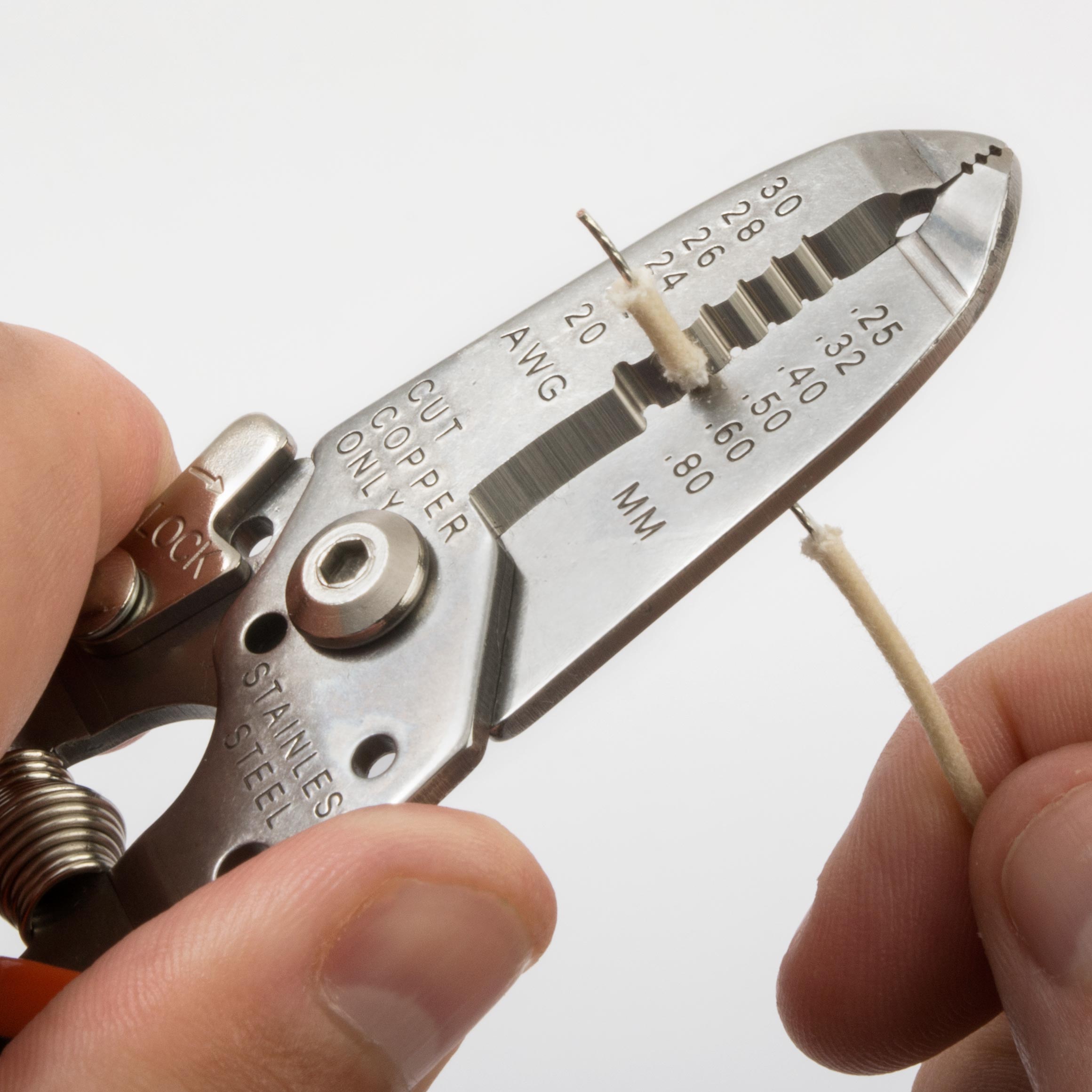
And then I'm just going to heat the wire and run the solder up the length of it. You don't need a ton, you don't want to make it any bigger, you just want to add some more solder to get a good solid connection and to make it easier. Pre-tinned wire will flow quicker and heat up better than un-tinned wire. It'll still conduct electricity in the same way. So for that example and then another thing that sometimes I see, is people using the wrong gauge wire strippers [on-screen text reads: Fine-gauge Wire Stripper at stewmac.com].
These are great for electronics. They start at 20 gauge and go all the way down to 30. 30 is very small wire. Probably not going to see that in a pedal kit. 24 gauge wire is very popular in all pedal kits. Again, it's the right size for what we're building. So the thing I see is people either using too big of a stripper, which you end up fighting your jacket and you might not cut it all the way cleanly, and then you're pulling it off and you can kink your wire or what have you.
And then the other thing that I've seen is people not paying attention and using too small. So I'm going to strip this at 26 say, and again it's harder than it should be, because I also cut a bunch of those conductors. So you can see that Rachel, there's like two left. That's not what you want. You want to trim it, trim that jacket with the proper gauge. So we've got 24 gauge on our strippers, line it up with that wire, and it should just come off as easy as that. We recommend 3/32nds. You don't have to measure it, just don't go too crazy getting a bunch of exposed wire, because you'll lose length of your actual component, and create a possible short if there's a bunch of exposed copper.
So again, each wire, I'm going to just trim the end off where I can get it through the eyelet or into the jacket, without having to worry about extra wire hanging off, and without having to worry about melting a bunch of this jacket. If you do melt the jacket, not the end of the world, it's not going to look as nice and it's going to smell funny. And plastic in your circuit is not a great thing, but it shouldn't cause your pedal to fail, if you melt the jacket.
Pete: So Tommy, what can people look for, to kind of indicate to them that they've stripped it correctly? Are there any kind of key things to keep an eye out for?
Tommy: Yeah, I mean if you can see that, and again, I'm going pretty quick. It's a nice clean cut. I didn't damage the innner conductor. The tinning is all still intact, so it looks like kind of one conductor, but it's 8 or 10 or whatever. And again, this one you can see is kind of on an angle, doesn't really matter. The big thing is I haven't damaged the inner components and I don't have big threads of plastic all over the place, which mostly just gets your soldering iron dirty. You don't want plastic on your soldering iron tip. Plastic doesn't conduct electricity very well or heat.
Rachel: Why did you hold that [inaudible 00:35:13] you just cut up [inaudible 00:35:16].
Tommy: Sure.
Rachel: Let's see what that's looking like up close. There we go.
Tommy: Yeah, so that's a nice length there. So we are just going to get all these wires trimmed real quick. I guess I don't need my optimizer for this. I just like wearing it.
Pete: While you're finishing stripping the ends of those wires. We had an earlier question that I missed, again from Scout. "Do our kits use batteries?"
Tommy: No, none of our kits are available as is with a battery option. Now we do sell DC jacks that I believe would fit right in the pre-drilled enclosure and you could wire them up with a battery. We sell the nine volt connections as well. But again, these are all designed to just work with a center negative nine volt adapter, which is the most common pedal power you can find out there. We sell them. I think we sell the one spot and we may sell another D'Addario or something, but they're widely available. It's the most common for pedal boards too, to have that center negative. That center negative DC's power supply. That's a good question.
Pete: All right.
Tommy: There are kits that have battery power. Actually that phaser kit that I built has a battery in it right now.
Pete: Is there any advantage to one over the other?
Tommy: Yeah, so battery power is not always going to be as stable and it's not going to be the same every time. Sometimes people want lower power. Old fuzz pedals, people love them when their battery is just about to die. It just has this magic biting beautiful sound. But for a pedal like this and really for all pedals, they're designed to work with nine volts, so that's what you should give them. All right, so we are ready to install our wires. We're going to put the 8 2 inch leads in and again, doesn't really matter which one you do first. I like to just start on the top and work my way down.
So for these, I like to put them in from the bottom and this is in the instructions as well. And I like to get that conductor, that lead and the jacket as far down on the board as I can. Can you see that Rachel?
Rachel: I can.
Tommy: Far out. So that way you're not going to have a bunch of exposed copper. That'll help with both noise and avoiding shorts. And then my favorite trick here is to pull this over and tuck it either in between a component, or just down so it holds itself in place. So now I don't need to hold it and try to solder and add solder and burn myself, or have it fall out while I'm soldering. That is a trade secret for you right there.
Pete: That's a pretty good tip, [inaudible 00:38:36].
Tommy: So I'm going to do one at a time and I'll show you why. I'm going to add a little more there. So for these leads, these jumpers, you're going to need probably just a little bit more solder than you used for these components. Still doesn't need a ton if you can see that, Rachel, it's not globbed on there, it's not overly bulbus or anything, and it's not pouring out the back of the eyelet. So again, it's not a ton of solder, but it is just a bit more than I used on those other components.
So now that first one is going to help me on the next one. I'm going to add my lead through the board. Easier said than done I suppose. Come on. There we go. And then I'm going to wrap this lead under that one and hold it in place. Just little things like that that can make your life easier are really good. And everyone has their own little favorite tips and tricks for soldering. This is by no means the only way to do it, it's just the way I've found that makes my life a little easier when building a pedal kit. So I'm going to do that with these next two. Again, these middle two on that top row are not for these jumpers, therefore the diode, the LED... Sorry, which is a diode, but it's your indicator light for whether your effect is on or off.
Pete: Hey Tommy, we have a bit of an off topic question, but I think it's a good question for you with your repair background. Gary Winthrop says, "A sound guy rested a cable against the tubes in the back of my amp and melted rubber onto one really badly. Anyway I can clean it off safely?
Tommy: Let it cool. And you could probably try just scraping it off lightly with your fingernail. You don't want anything real abrasive on that glass. You could try some solvents, if that doesn't do the trick. But I would really advise you to find a new sound guy. Sorry Gary's sound guy. But I mean the thing is tubes are disposable, they wear out. So unless it's like a real great new old stock preamp tube, it sounds like if it was that hot, it was more than likely a power tube, I'm guessing. You may just get a new set of tubes. It looks like I lost one of my leads. What happened here? I'll figure it out. Or maybe I just didn't cut enough. I thought I did.
Susan: Let me know if you need more. We'll get it.
Tommy: Thanks Susan. So I'm going to get this bottom row going again. That first one, I'm going to peel back and wrap it around, so it stays in place. Well, it's not wanting to behave here, get you in there. Sorry, if that's real glary, Rachel.
Rachel: This is actually pretty all right.
Tommy: All right. There we go. Nice and stable. Susan, I think I do need just a tad more wire.
Susan: You got it.
Pete: Was the one that you used as an example not an extra?
Tommy: That was my extra I thought, but I just... Not a math major.
Susan: It might have fallen down or something.
Tommy: All right, so again, I've got my first lead to act as a helper for that one to stay in place. Pop that in there, solder that up. I kind of like the off topic questions.
Pete: You heard it, audience. What off topic questions do you have?
Tommy: Yeah, let me have it, Scout.
Pete: You may have opened Pandora's box.
Tommy: All right, so I just got to cut one more lead real quick and we'll finish this up. And this is the end of this step, which is essentially the end of our episode tonight. Those last two leads are going to be for your jack's and for the foot switch, which is what we will do in the next episode. We're getting very close here folks, so thanks for sticking with us.
Pete: This is a great question here from Clark Babin. "What is the validity of skin oils on a tube burning out the tube?
Tommy: Personally, I have never seen a tube fail from the skin oil, but I have heard anecdotal evidence that it can happen. It makes sense to me-
Pete: But I think we're getting ahead of ourselves a little bit maybe for some of the viewers who aren't familiar with this idea, can you explain exactly what the question is asking.
Tommy: The idea is your skin naturally has oils and you've got a glass tube, like a light bulb that's going to be heated very hot. It's going to have 400 volts of DC current going through it, is that going to make them explode or fail or whatever? Like I said, I've never had it happen to me personally, or heard of any repairs I've done for tube swap for a customer. I've never had that be an issue. That is not to say it can't happen. I've just only heard anecdotal evidence of that. Never seen it.
Pete: All right, so is that the last lead there?
Tommy: That was our last lead. I'm going to shut off our soldering iron. I believe we are all done for this episode. Again, we've got all our components and all of our leads on the main board, everything installed except for the LED, which will come. It's one of the last steps, just because it goes into the enclosure itself.
Rachel: Everything is looking good.
Pete: All right, so next episode, we're going to be finishing everything up, right?
Tommy: Yeah, you got it.
Pete: We got the last couple of steps.
Tommy: Yep. We're going to get our foot switch, our jacks and our LED installed. I'm going to put this thing in the enclosure and see how it sounds.
Pete: All right. Well-

