Oak Grigsby 4-way 2-pole Lever Switch Instructions
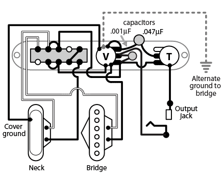
Installation and wiring diagram for the Oak Grigsby 4-Way 2-pole Lever Switch.

Position 1 Bridge pickup
Position 2 Neck and Bridge in parallel (standard Tele neck/bridge configuration)
Position 3 Neck pickup
Position 4 Neck and Bridge in series
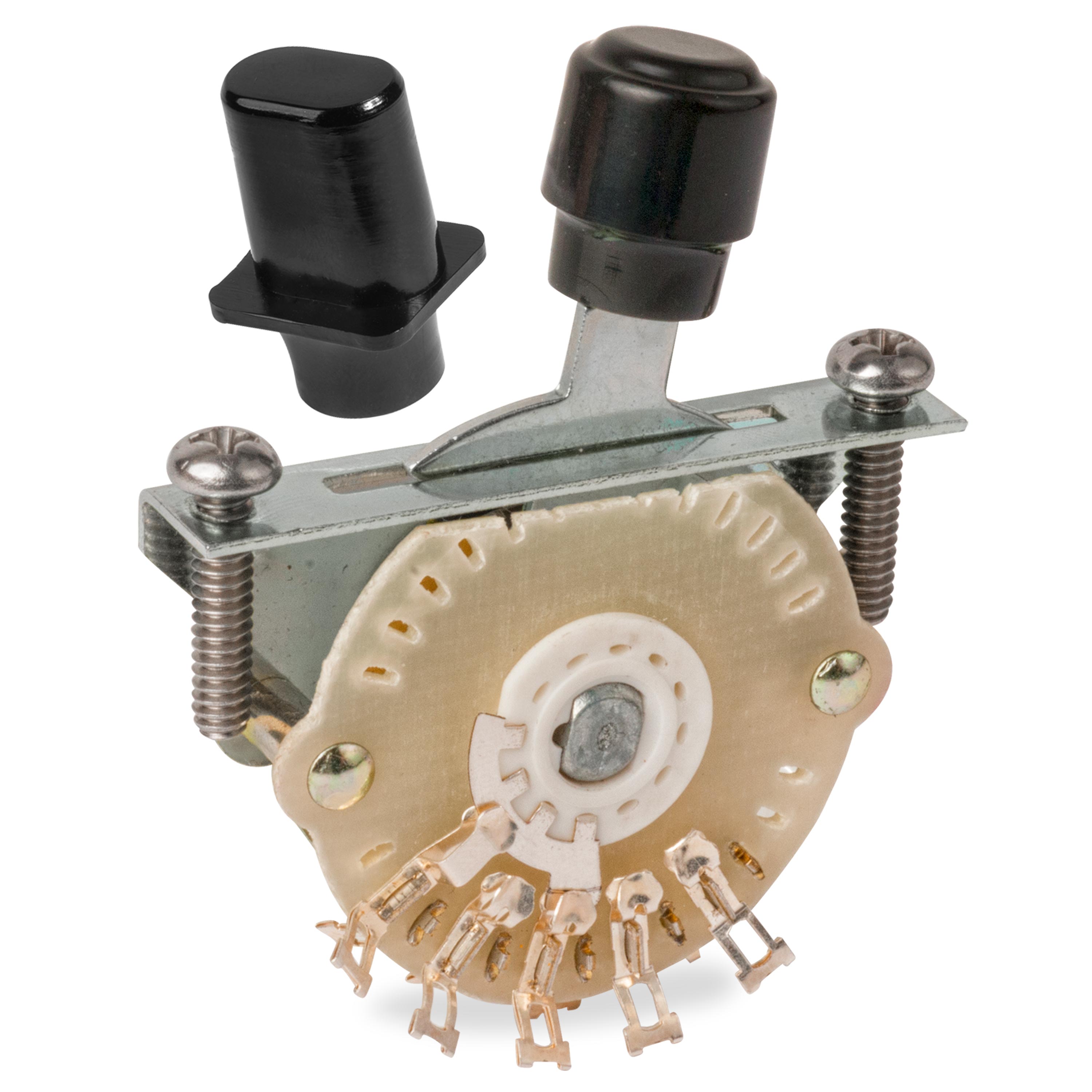
The lever switch can be installed with the spring facing either side—there's no difference, electrically.
Minor modification to the neck pickup is necessary for this setup. The cover must be disconnected from the black lead of the pickup, then run to the ground with separate lead wire.
String ground on a Tele is usually made by the metal baseplate of the bridge pickup contacting the metal bridge. If your pickup doesn't have a metal baseplate, run a string ground wire from the back of the volume pot to the underside of the bridge.
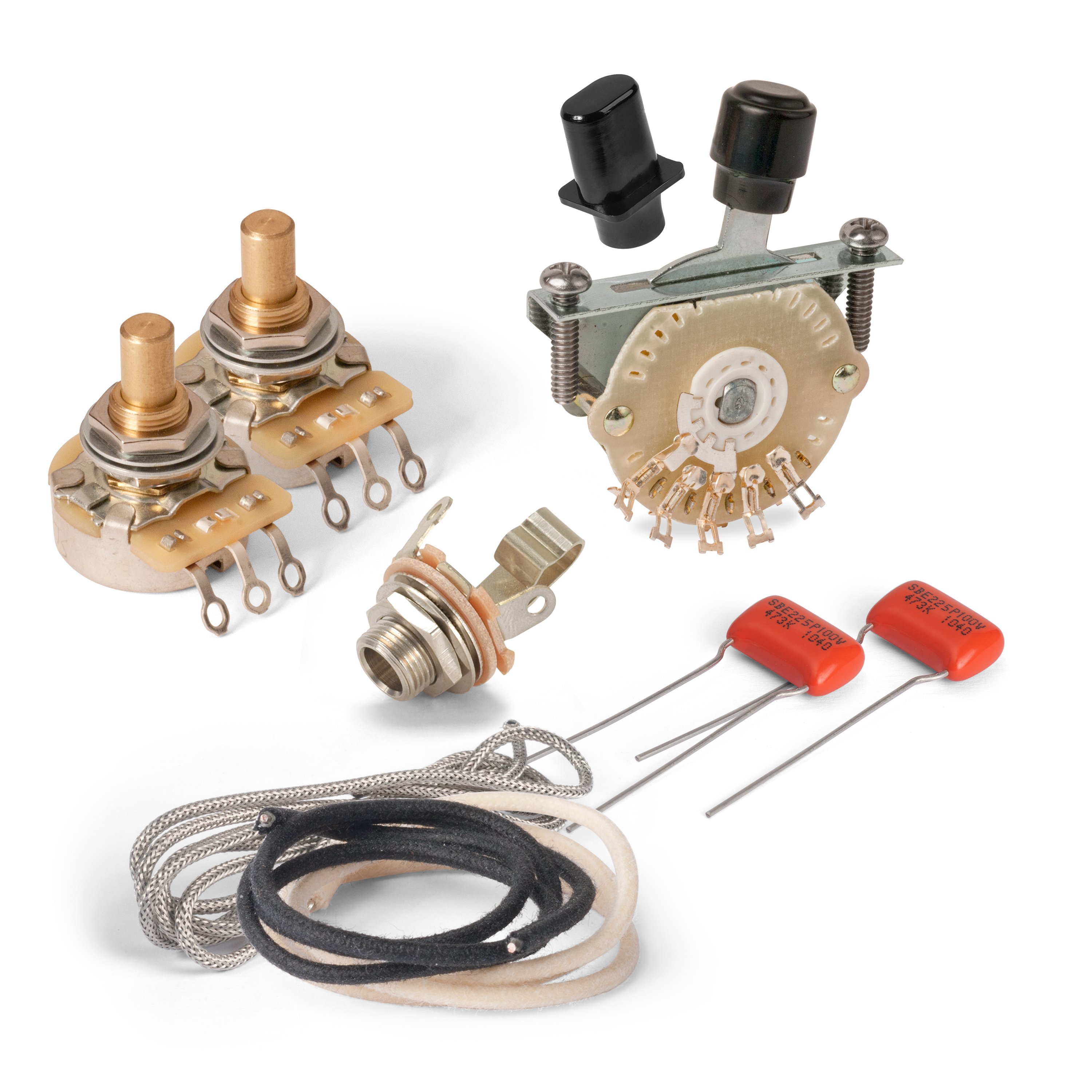
Reduce unwanted electrical noise by using shielded coaxial cable for your longer wiring runs (for example, the connection between the controls and the output jack). Coaxial cable contains a center "hot" conductor which is shielded by an outer braid used for the ground wire.
For short connections between components, use standard non-shielded wire. Typically, white wire is used for hot and black for ground.

