Episode 1: PREPPING THE CAB+BOARD
V-AMPEP1
If you've ever thought about building your own hand wired amp, but weren't sure where to start, this replay of our live build-along series has all the tips you need.
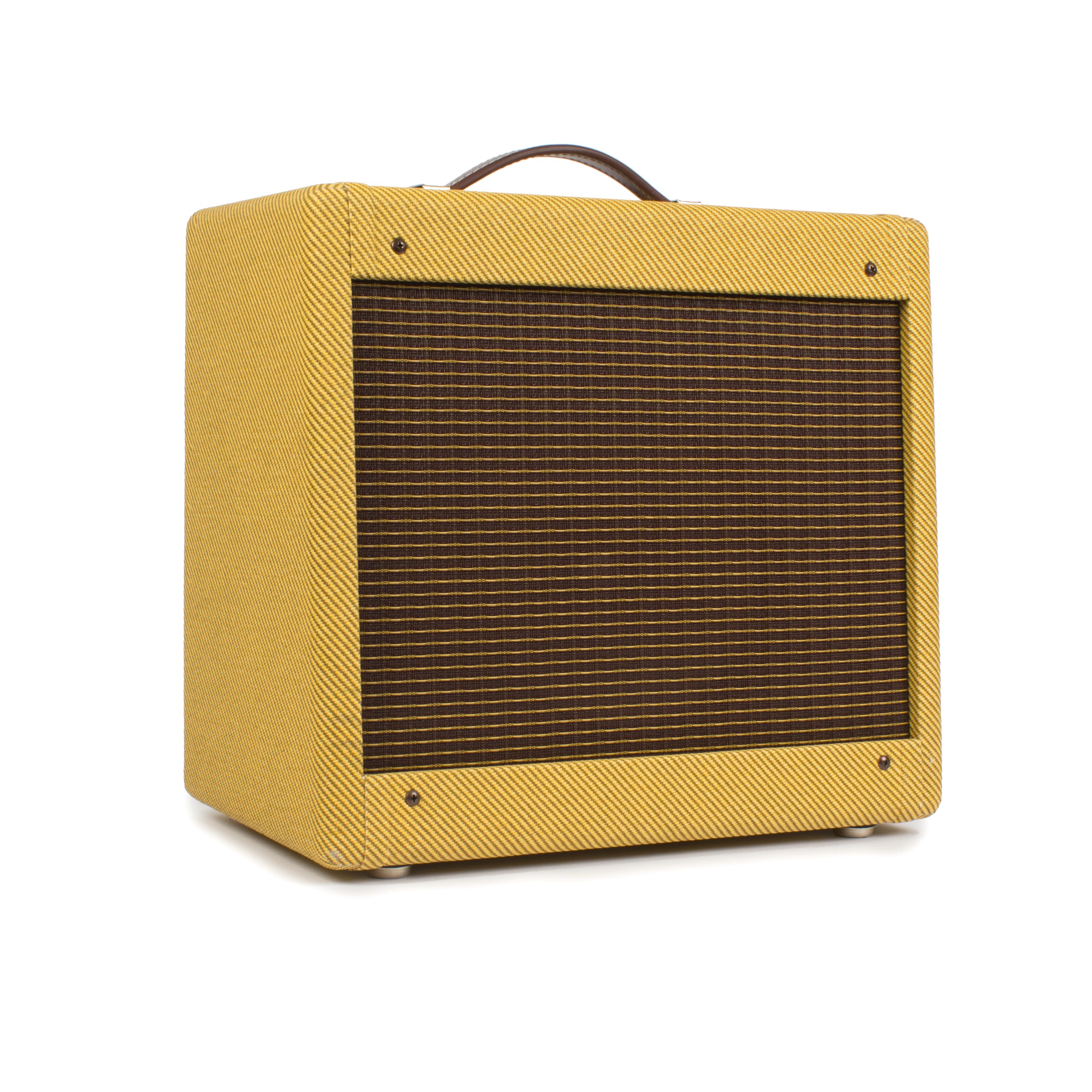
In this 5-part series we show you step-by-step how to build our '57 Mini Tweed Amp Kit, with the famous 5f1 circuit. Even if you're a complete beginner don't worry! In this first episode we go over everything from safety, prepping the cab, setting up the eyelet boards, and even some sound demos!
Video Transcription
[on-screen text reads: '57 Tweed Amp Kit Live Build-Along - Episode 1]
Pete: Welcome, welcome, welcome everyone. Thank you for joining us. We're live here in StewMac studio. My name is Pete. This is our first episode of our Live Build Along Series. We're going to be building our 57 Mini Tweed five watt combo amp kit. Joining me today, excuse me, is of course Tommy Stumpp.
Tommy Stump: Hey everybody, I'm Tommy.
Pete: Our videographer Rachel, and our director Susan.
Susan: Hello.
Pete: All right. Like I said, we're going to be building our 57 Mini Tweed five watt combo amp kit over the next five episodes. This is episode one. Before we really dive into it, we're going to be prepping the cabinet this episode, and as well as the eyelet boards. But before we get into that, I think that it'd be great to have Tommy demo this amp kit for you a little bit. I'm going to toss it over to Tommy now.
Tommy Stump: Hey everybody. This is the five watt amp kit that set the stage for all the other ones. The great practice amp, great for studio use, tons of different variety of tones you can get, just playing with the volume on your guitar. I've got this one set pretty high. Depending on how my guitar is set, you get more overdrive or great little clean tones. We've got some good clean. I'm about halfway up on my guitar. If I go more, you can hear it start to get that great overdrive that people like Eric Clapton, Joe Walsh were really into. This was an iconic amp. A lot of great studio musicians used this throughout. From the '60s on, Keith Richards still uses one. Jimmy Page used a lot of smaller amps for some of those huge sounds on Led Zeppelin.
This is a great little amp, for sure. I love it. I have one on my bench all the time for testing out pedal kits and stuff like that.
Pete: Yeah, you mentioned some of these great professionals using this amp. Can you tell us a little bit about the history of the amp itself?
Tommy Stump: Yeah, it was introduced in the 50s as a student amp, low wattage. The idea back then was to have an amp just be really clean. And then they figured out pretty quickly that if you crank it up, it really overdrives the circuit. And you can get just beautiful massive tube overdrive tones. And then if you pair it with pedals, you can really send it into outer space. It's a North American hand wrapped tweed made in the US, beautiful tweed cabinets on these things. You can lacquer them if you want. A lot of people think that's pretty cool, but it really is just a simple circuit, great for a first time amp builder. And again, it's an icon for a reason, for sure.
Pete: Nice. Yeah, you mentioned it was originally introduced as a student amp. Why then so much interest from all these professionals?
Tommy Stump: When you're in the studio, your overall volume can be a thing you have to work around you. If you have a big amp, you got to crank it really loud, and it's painful for the engineers to be around. Whereas something like this, you could sit it right next to the player, crank it all the way up, and you're not going to annoy that the neighbors next door, the people trying to write songs upstairs, or what have you in the studio.
Pete: All right.
Tommy Stump: And it's just perfect for a bedroom, or for your office, or what have you, just to plug in and play a little bit. And again, you can crank it up and still not be in pain like you would with a big full stack or something. That's as loud as it gets pretty much.
Pete: It sounds great. Nice. All right. Yeah. Before we really get into it, let's take a look here at what we've got. You said we've got 57 tweed. It's the original 5F1 circuit, right?
Tommy Stump: Yeah. From the '50s, the 5F1 circuit was just the designation from the manufacturer. And again, it had some younger brothers and some older brothers. Later iterations included a tone knob. This just has volume which is fantastic. Again, if you're in the studio, you want to be able to replicate your settings if you can, makes it super easy. This just uses a tube rectifier, a power tube, and a preamp tube which we'll talk about what all that means later, but later ones included vibrato or a tone knob, but this is revered as maybe one of the best circuits of this kind of amplifier.
Pete: And before we get any further, I do want to say hi to everyone who's watching along. And we do see your comments. We welcome any questions you may have. It's why we're doing this live, so you can build along with us and answer those questions on the air with you. Otherwise, we just shoot it and release it later. Please feel free to send in your questions, and thank you for joining us.
Safety first
While Tommy is setting up over there, there's something that we do need to get into before we really go any further. That is basically the voltages we're dealing with in building an amp can be very dangerous, and even potentially deadly. It is very, very important to pay attention [on-screen text reads: Amp voltages are seriously dangerous].
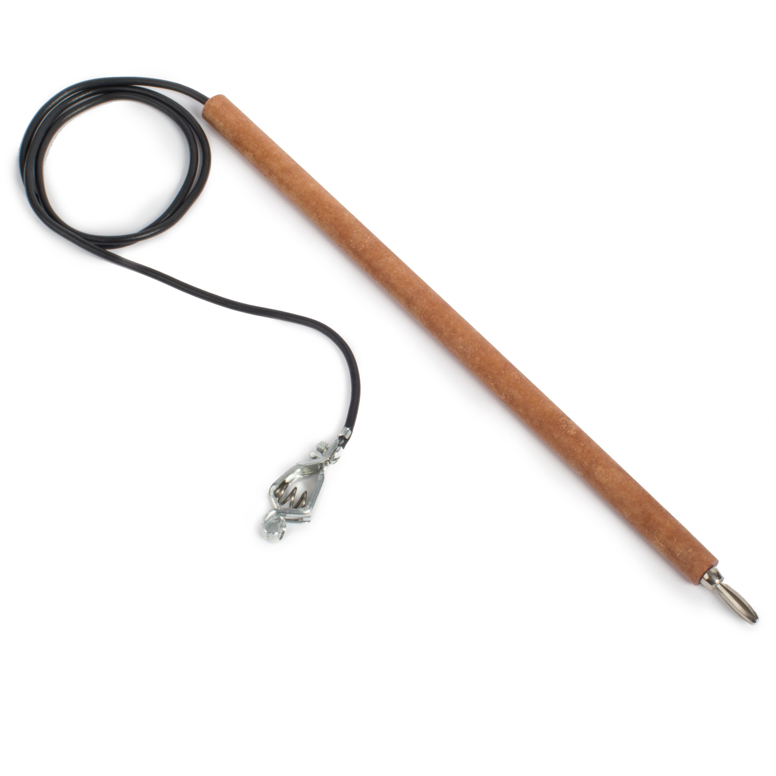
You don't want to just go sticking around inside an amp that's been used or has been on. Because the capacitors in an amplifier, they will hold on to the voltage, even after it's unplugged. What we're going to do now is Tommy's going to go ahead and show you how you can safely work on an amp that's been plugged in.
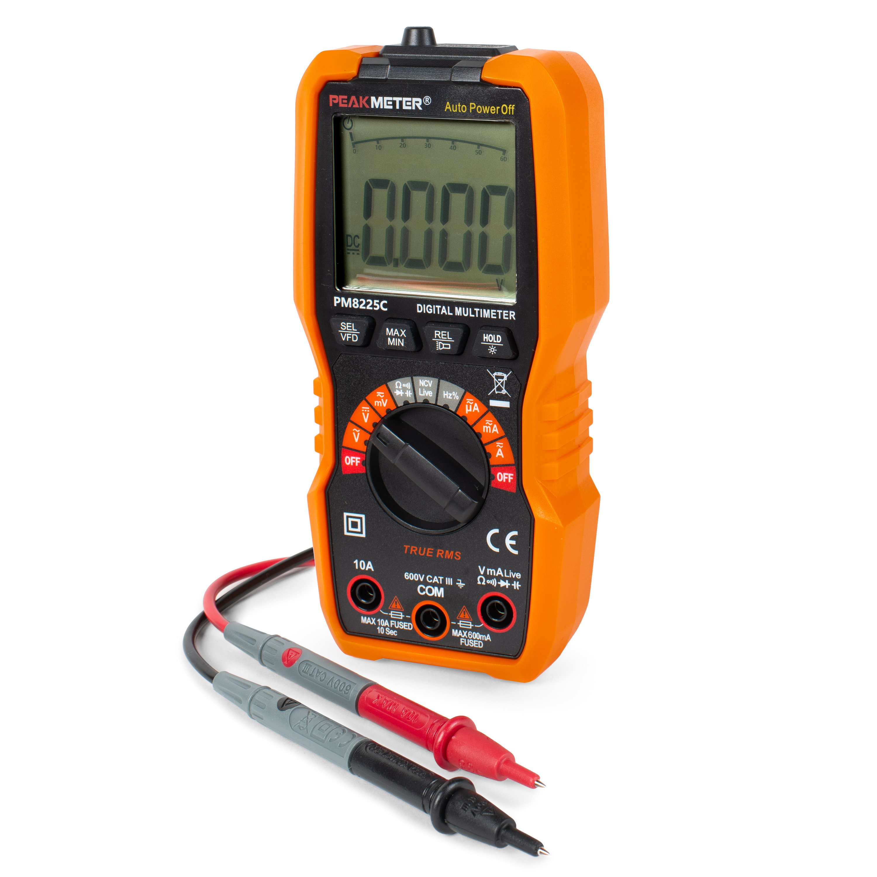
Tommy Stump: Right. This is the amp I was just playing. What we're going to do is get our digital multimeter, and I've got a test lead on my negative or black lead. I'm going to clip that to ground. In this amp, the steel chassis is everything is grounded through that as well. You can just clip it onto the chassis if you like, which I'm going to do here. Then I'm going to make sure it's grounded by using a continuity test on my meter, and checking another known ground point, which it's not right there. It's good that I checked it.
Pete: Okay, so you're saying that that wasn't grounded where you had it on the chassis?
Tommy Stump: Right. It should have beeped when I tested that. So, let me get this red thing off of here.
Pete: All right.
Tommy Stump: Of course.
Pete: All right Tommy, we've got our first question here from-
Tommy Stump: Yeah, shoot.
Pete: ... big keg. They would like to know do we have a conversion for 240 volt.
Tommy Stump: Yeah, this amp comes with international tap hookups for the transformer.
Pete: Okay, great.
Tommy Stump: Almost all of our amp kits do at this point. We have a bunch of amp kits, and I think there may only be one that doesn't have international taps at this point. Again, I connected this in a better spot, where I know it's going to be grounded. And I'm not sure... Oh, the audio is just not working, so cool. The meter is just not going to beep when I have continuity. I've checked continuity. I've checked continuity here in my amp, and we're good. What we're going to do is check our DC current or DC voltage at the filter capacitors. This is where the most voltage is going to be. It's what you really need to worry about. I've got my amplifier off.
Pete: And can you point out those filter capacitors for everyone?
Tommy Stump: These big blue guys here are the filter capacitors. They store the high DC voltage, and I'm going to check at that first point, which is where the highest voltage is going to be. And you can see if I can get that in there, right? It may be that my power tube just pulled all that voltage out right away. In a properly working amplifier, your tubes are going to pull the voltage out for you. But if you need to work in an amplifier, it's probably because something's gone wrong. And you can't rely on those tubes to pull that voltage out for you. It's vital that how to do this. And again, we're not trying to scare you. We're just trying to give you the best knowledge base and create some of the best habits that we can if you're going to be working in an amplifier in the future.
Pete: Yeah, and I've got a good question for you. Are solid state amplifiers as dangerous to work in as a tube amplifier?
Tommy Stump: Yes.
Pete: It's all about the capacitors.
Tommy Stump: Nearly every solid-state amp has filter capacitors in it. Filter capacitors are what take your high wall voltage, which you can see we're at 380 on our volt meter. That's enough to stop your heart. And again, not trying to scare you. Just so you know what's going on. What I'm going to do now is attach my snuffer stick, which is two resistors wired in line to ground. And that is going to quickly drain off that high voltage. Until your caps are drained, it's a really good idea to either stick your other hand in your pocket, or just keep it behind. You don't have both hands inside the chassis at the same time. If you touch the wrong two points, you're going to send that voltage through your hands, through your heart.
Pete: And for anyone following along with us at home in the instructions, you can find all this information on page six I believe.
Tommy Stump: Right.
Pete: Yes.
Tommy Stump: Now, I'm testing that first spot again and we're down to 14 volts. It's just a little more that's in a common battery. You're not going to hurt yourself certainly with that amount of voltage. Now, it would be safe to work in this amplifier, whether you're swapping out resistors or just troubleshooting. You really want to do that anytime you're going to be working inside of a circuit that's been fully live.
Pete: All right and...
Tommy Stump: I just wanted to show you that before we get too far into this.
Pete: And what setting are you using on that multimeter, the test kit?
Tommy Stump: This one has a few different settings for DC voltage, direct current voltage. I was on 600. Anything over say 400 would be appropriate for checking the B plus, or the high DC voltage in a circuit like this. It depends a bit from circuit to circuit. The meter we have is 600, which is appropriate for any of our amp kits for checking that high voltage that we refer to as B plus voltage.
Pete: Absolutely. And speaking of our amp kits, this is just one of five amp kits we have in our icon kit series. Besides the 57 Mini Tweed five watt combo amp kit we're going to build, we also offer a '59 Tweed 15 watt, '62 Brit-Plex 45 watt, '65 P-Reverb 15 watt and a '66 D-Reverb 22 watt.
Tommy Stump: Yes, indeed.
Pete: And speaking of icon series here, you mentioned that it's got this really great tweed cabinet, but what can people expect to find component-wise that's going to go inside?
Tommy Stump: Yeah. It's all good stuff, orange drop caps, sprague item, bypass caps, got the vintage spec carbon comp resistors, which are what was used by everybody for the first 25 years of these things being popular, until better components got more invoked, but it's all good stuff, vintage eyelet boards. Everything in it's good. And then obviously, you can upgrade whatever you want, but I built one of these just stock, and it sounds good.
Pete: And when you say better components came along, just technological advances?
Tommy Stump: Yeah. Carbon composite resistors were used, because they were cheap and widely available. They have a little bit more noise than say metal film resistors, which now are very popular among boutique builders. Upgraded tubes, upgraded caps, all sorts of things like that you can do, but they sound good just out of the box for sure.
Pete: All right. Another quick question here regarding when you were testing the voltage, or the capacitance. Let me clear that up. Were you testing the capacitance of that capacitor, or the voltage?
Tommy Stump: We're testing the b the DC voltage referred to as B plus voltage.
Pete: Okay. The question is... well now that I've lost it, are you checking both sides of the capacitor?
Tommy Stump: No. One side is going to show your voltage, the other side is ground. You just check the positive side. You check it at where the rectifier hits the first filter capacitor, which you can see on a schematic, or you can see in a wiring diagram usually. In our case, the rectifier tube comes straight out with high B plus voltage that's pulsing, and the filter caps take those pulses and turn them into a smooth supply for the rest of the circuit.
Pete: Right. And if you want to view the complete wiring diagram, we have that. That's on page eight in our instructions, but I think it's time we get started on preparing the cabinet, right Tommy?
Tommy Stump: Yeah, I think that's it.
Pete: All right. I've never built a an amp before, so this is something I'm very excited to get into. What advice would you have for someone who may be a little nervous about starting an amp build if they've never done one before?
Tommy Stump: With our instructions, you really can be an absolute beginner and have success, and have a great sounding amp at the end. You need to be sure you're taking your time. You need to be sure you're not working when you're overly tired, or trying to do too much at once. You want to keep a tidy bench, which I don't know if you saw that, but I've moved all that stuff that I was done with back, so I have a clear bench. You don't want to lose anything, and you also just want to keep as organized as you can, so you're efficient with your time.
Pete: Just to answer Bill's question really quick. Apparently, he's having some issues watching the stream. These will be on our YouTube channel that you can always review go back and watch whenever you feel like it. Not to worry, they will be available.
Step 1: Mount the power cord clamp
Tommy Stump: I'm just going to remove these four screws from the top back panel, and the two from the bottom panel. You don't really need to remove the bottom panel, but it just makes it easier to get in there. Do excuse the noise here for the next couple seconds.
Pete: All right. Yeah. While Tommy's taking that off here, you can join us in these great color, very detailed instructions. Step one will be starting on page nine.
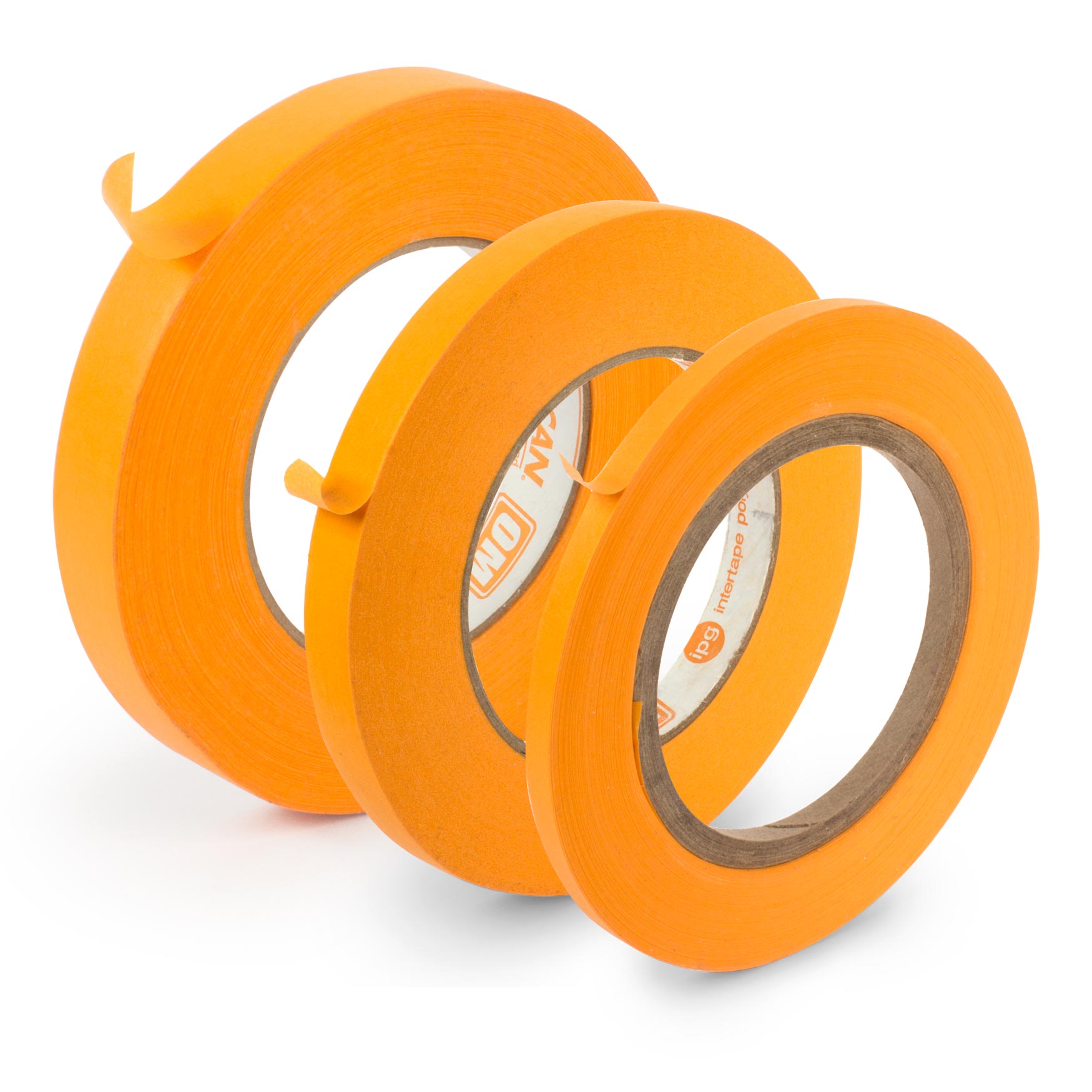
Tommy Stump: Yeah. Step one is essentially prepping your cabinet. We're going to mount the screw for the power cord clamp which is oops... I need to just move my drill bit. I've got a drill bit. I'm going to drill a pilot hole for this screw, and you can see I've masked it off ahead of time to the depth I want. Again, this is just a pretty standard wood screw. It doesn't need to be perfect. You're probably not going to break this screw off in pine, like you would in maple in a headstock or something. You can see, that's about the right depth. And I flagged it, so I just don't drill all the way through. You don't want to drill through the tweed.
You're going to quickly end up having a relic project, which we do have a cool thing from our friend, Daniel who did a relic on our tweed deluxe kit, which turned out really cool.
Pete: All right.
Tommy Stump: I'm going about two inches in, which I can show you Rachel. I'm going about two inches in. It doesn't need to be in any specific location. That just gets it, so it's not in the way. It's secure in case your amp falls, or gets tugged by the power cord. It's not going to rip it out and damage your actual amplifier. There we go, Bob's your uncle, got your little pilot hole. I'm going to get our screw bit back in here. Again, you don't really 100% need to do this first. It's just nice to get the cabinet prep out of the way first thing. You don't have to think about that at the very end when you're ready to test your amplifier out.
Step 2: Solder the speaker leads
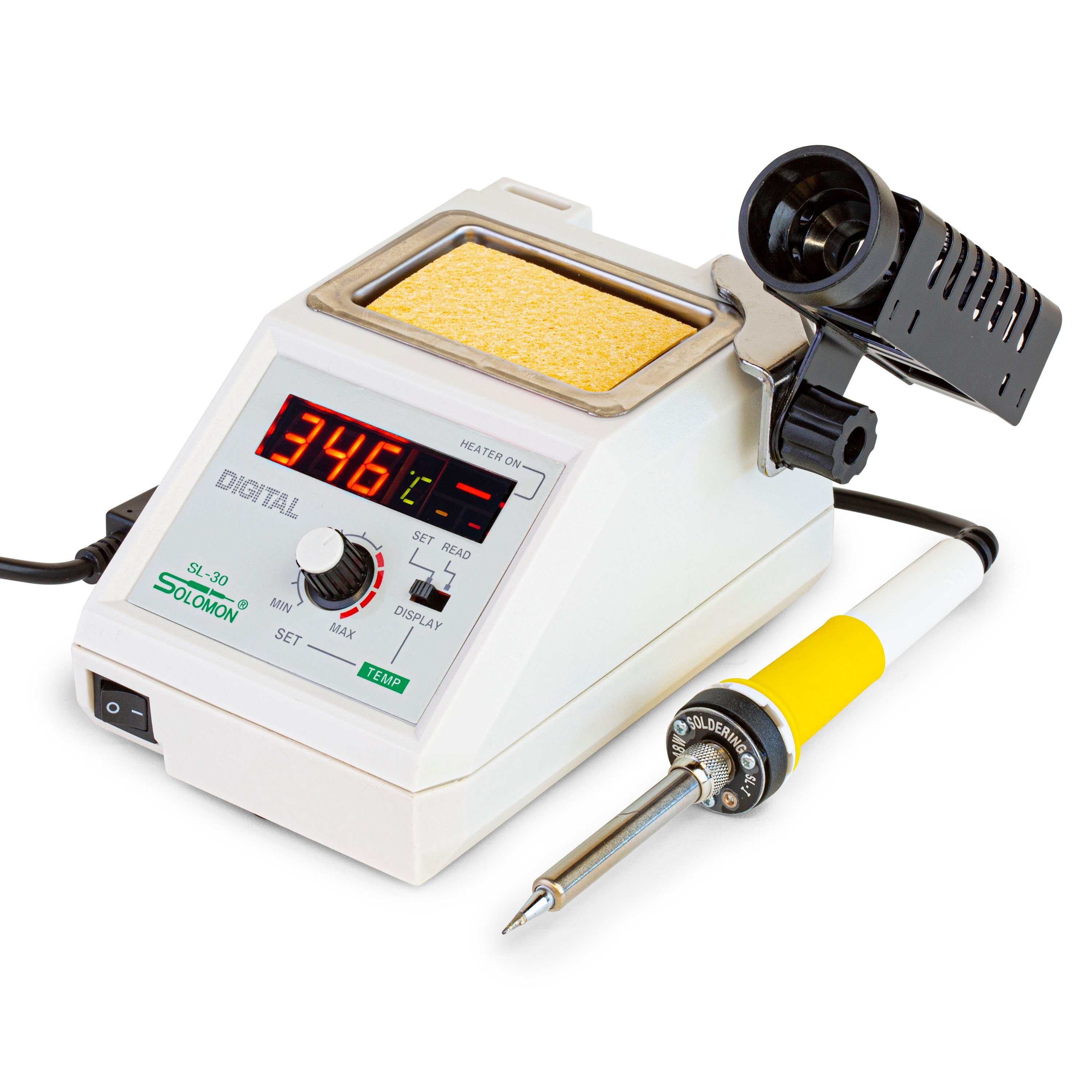
Pete: And I think Tommy's already got his iron on, but next we'll be doing some soldering. So, anyone who's following along with us, you can feel free to go ahead and turn on your soldering iron and get that warming up.
Tommy Stump: Yeah, we still got a minute, because you still had to prep a thing or two still, but we're getting close for sure. Now, I've got that. I'm going to set the cabinet. I'm going to set the panels for the cabinet aside. I'm going to grab my speaker. These come with a nice 4-ohm ceramic Jensen 8-inch speaker, really close to what was in the originals.
Tommy Stump: Yeah. And again, I do get questions every once in a while about which way does it go? Does it matter? That's just a sticker, it doesn't really mean anything. You can mount it however you want. I like to be able to read it, so I'm going to mount it like this. Now, what I'm also going to do first is solder my speaker leads. You can see this fits right on these mounting bolts. Should be really easy to get this installed. It's good to check that first in case you need to do any work on those bolts. I've got my iron turned on, set to about 370 Celsius or 700 Fahrenheit. While that's warming up, I'm going to get my little protection ready for my speaker hookup.
I like to use a post-it note. It fits right in there just perfect. You can stick it onto the cage of the speaker, so it's not going to go anywhere. That'll protect your speaker cone from any stray solder or anything like that, and wire.
Pete: All right. You had mentioned it's a 4-ohm speaker.
Tommy Stump: Mm-hmm.
Pete:
Is that standard for this kit? I'm assuming it's standard since what comes with it...
Tommy Stump: Right. This kit, the output transformer is a 4-ohm output transformer. Really, important to match that impedance. You can get other output transformers and other power transformers if you decide to start really modding this kit out. But as it is, you'd need to use a 4-ohm speaker with the included power output transformer. We've got push-back wire for our speaker leads. We're going to twist those together. Twisting these is for tidiness, not so much for noise cancellation. You don't need to go crazy getting these super tight. You just want it to look nice. Once I've got those twisted, I go till there's about two inches on each end, which I don't know if you can see that, but no need to go crazy or make it perfect.
You just want to have it nice and tidy. Then I've got these splayed out. Now, I don't know if you can see on the camera, but these terminals are labeled plus and minus. Standard wiring white is your plus, or your positive. So, that's how we're going to wire it. I can see my iron's nice and hot. What we're going to do is feed these through the respective lugs. Now, this is just push back wire. You don't need to trim it. You can strip that jacket if you want. But for most of this kit, you don't really need to. Again, I'm going to feed these through here from the bottom up, so I can see the lead.
Pete: When you're setting these up to be soldered, what are you looking for as far as what will really facilitate a good solder joint?
Tommy Stump: A good mechanical connection is a good building block for an electronic connection. I can see this wire is making good contact with that metal without solder. Then what I'm going to do is just add some solder to fully connect them, make sure they stay together for a good long time. These connections really need to be good and strong. This is going to vibrate the most out of any connection in this kit. You want to have a really good connection. You're going to use a pretty liberal amount of solder on these and a couple other joints in this kit. Doesn't matter which one of these lugs you go to on the speakers.
Pete: That was going to be a great question we got from little coating here. Any difference from the side and upper of each lug?
Tommy Stump: Nope. Essentially, that is so you can put these in a cabinet, like an extension cabinet. You can wire them in series or parallel. It's a ton of information about how to do your calculations as far as multiple speakers elsewhere online. But essentially this kit, you're only going to have one speaker in it. Again, I'm just making that good hot connection. You can see both of those are nice and shiny. Once they've cooled, I'm going to give them a little tug, make sure we're good there. A good solder joint should hold a fair amount of pressure. You don't need to go crazy tug testing everyone, but these are a good one, because the speaker vibrates anytime you're playing.
Pete: And for more really great tips on soldering, you can turn to page 16 in the instructions. There's a lot of really great tips and just I guess trade secrets, what you want to look for.
Tommy Stump: Yeah, for sure.
Pete: ... that'll indicate you've got a great solder joint. Yeah.
Tommy Stump: Now, we're going to solder our speaker plug.
Pete: All right. Yeah, moving on to page 10, that's step three.
Step 3: Solder the speaker plug
Tommy Stump: Yeah. And again, we're going just step by step through the instructions live for you guys. If you're following along or if you're doing this later, these instructions come with every kit. They're also on our web page for free if you want to just follow along. Again, we've got our other end. I've got a helping hands here. This is really nice to have for a couple of the smaller connections that are off the eyelet board. I'm just going to stick my plug in there. And again, our white is our positive, so that's our tip. Strip that back pretty far, just peel it back, and feed that through the center. You want to be able to see that coming through the end. There we go. I don't know if you can see that on camera Rachel.
Rachel: I can see it pretty well.
Tommy Stump: Great. My conductor is coming through the end, and I just want that tip to make a connection with that center conductor. I'm going to flow that solder onto the very end. I'm going to avoid getting solder on the outside, because it'll interfere with the actual plug inserting into the jack in the amp.
Pete: Hey Tommy, if you were to accidentally get some solder on the outside of that plug, what do you recommend to remove it?
Tommy Stump: You can file it. You can use a solder wick. Solder wick is probably the best tool for that. Any filing could lead to corrosion, things like that, but this looks pretty good, give it a little tug. It's not going anywhere, and I'm just going to check that I didn't get any excess on the outside by plugging it into the actual jack, and it just goes right in. We're good there.
Rachel: Can you do that one more time?
Tommy Stump: Sure, yeah, yeah. This is the speaker jack that we're going to install later in our speaker plug, and I'm just going to plug that in just to be sure it fully seats in there, and that is good to go. Now, all right, our other connection is going to be our outside connection, the sleeve. I'm going to cut that to length. The black connection can come up around the outside of the sleeve, no problem. Again, I'm going to get that in my helping hands, and I'm going to use the other one to hold it in place like that. And then solder that guy on there. It's not wanting to stay. Let's get it going. These are pre-tuned push-back wires, which is nice, helps you work a little bit quicker.
I'm just going to hold that in place, while it solidifies. And I can see that's a good shiny joint as well. We're good there. What I'm going to do is just check those to make sure there's no short. If you're a beginner, I really recommend checking your work as you go. It'll help you avoid any frustration in the end stages of your build. Cool. I'm just going to check here. Yeah, and I can see that I don't have continuity between the outside and the tip. Super important, means my speaker's going to work. We are good to go with that step. What's next Pete?
Pete: Well, first, it looks like we've got a couple questions here. Saul is asking, is that a better connector than a quarter inch standard instrument connector?
Tommy Stump: Essentially, it's the same. It's an unbalanced audio connection. Meaning, you have a tip and a sleeve connection. And in this case, they're six and one half dozen the other. It's smaller which is nice for a small chassis like this, but essentially, it doesn't make a whole lot of difference tone wise, or anything like that. You could certainly update it to a quarter inch if you want, but just keep in mind that real estate is everything when you're working in a tiny little cabinet like this. So, a smaller connection like this is better than a big connection like a quarter inch would be, but some of our other amp kits have quarter inch connections for the speaker. That's a good question.
Pete: Right. All right. Next after we've got the speaker plug soldered, moving on to step four, installing the speaker. Yeah. Again, still on page 10.
Step 4: Install the speaker
Tommy Stump: I'm unscrewing all these 830 second nuts. These bolts are pre-installed by the cabinet maker. And generally, this will just slide right on. Every once in a while, one of these may be a little sconce or skew. You can just bend those back into shape with a nice little needle nose pliers like this. We didn't have to do that obviously. What I'm going to do, and I don't know Rachel if you have a good shot of this, or if there's a good shot from overhead.
Rachel: Yeah.
Tommy Stump: Cool.
Rachel: The overhead.
Tommy Stump: I'm just going to get these on finger tight. Not going to use a tool quite yet. This part doesn't matter which one you do, where or when, just get them on there.
Pete: Tommy, we've got another good question here from Rich Johnson.
Tommy Stump: Hi Rich.
Pete: What distinguishes this 5F1 kit against others out there?
Tommy Stump: Well, one thing for sure is our instructions and our support. We fully support all of our amp kits, pedal kits, guitar kits, what have you with our great technicians and customer service staff. Otherwise, this one comes with name brand tubes, a Jensen speaker. A lot of them really go cheap on the speaker, and a lot of them have lower quality cabinets. These cabinets are just fantastic. I hope that answers your question Rich. Now, we're ready to tighten our bolts. Now, there is information in the instructions. You don't want to just go willy nilly tightening them, however you want. You want to go crossways to avoid warping the speaker basket. If you do that and this gets distorted, the cone gets smushed and it'll distort your sound in a very unmusical, unpleasing way.
You want to get these tightened down. And again, I'm going to deviate just a bit from the instructions. The instructions are very cautious, and you can absolutely do it that way. But just to save some time, I know how it's safe to do this just from experience. I'm going to go until I start to feel a little bit of resistance, and then go about a quarter turn. And then I'm going to go across, and do the same thing. Again, the instructions say to go a quarter turn at a time working around the basket, and that is absolutely appropriate if you want to do that. Again, we're working on a clock, so I'm just going to get it done. Now, this one was already tight I just went until I got nice and snug. Then I'm going up here. Again, I'm not going in a circle.
Pete: All right. Luther Steve says, "Where's your nut driver?"
Tommy Stump: I don't have a nut driver long enough for these 830 seconds nuts for this...
Pete: Yeah, the...
Tommy Stump: But yeah, if I did have one, that would be way easier.
Pete: Yeah, the bolt sticks out a little too far.
Tommy Stump: Yeah, the bolts are pretty long.
Pete: ... for the nut driver to reach the nut.
Tommy Stump: And again, if that was something you wanted to do, you could shorten those if you've got the time and inclination and tools. But again, for our purposes, not really necessary. Again, I've got these good and tight. I'm only going around once because I can tell it's nice and sturdy.
Pete: All right. I think that is the end of step four there.
Tommy Stump: I believe that is.
Pete: Moving right along. Step five, we're going to glue in the tube replacement chart.
Step 5: Glue the tube placement chart
Tommy Stump: Yeah.
Pete: While Tommy's already got that cut out, so we don't have you find folks watch him use a knife or a pair of scissors, you can find yours to cut out on page 33 of the instructions.
Tommy Stump: Yeah. Again, there's two of these in case you screw up.
Tommy Stump: Yeah. This is another cool little thing in our instructions. Not every amp kit is going to have this. All the vintage amps generally had one of these stuck right inside the cabinets. It's another nice little touch. We're not using any crazy proprietary glue. Just regular old tight bond that I'm going to thin down about three to one glue to water. You can use rubber cement, you can use glue stick, whatever you want, but this is just we've got abundance of this around. It doesn't take much. Just about a quarter size in the bottom there, just a few drops of water. There we go. That's probably more like two to one, but no big deal.
Pete: This was something I've never serviced amps myself before, but something that I didn't realize was really standard, until Tommy was telling me about it. Is there anything more disheartening when you're working on an amp, and there's just no tube placement sticker in it?
Tommy Stump: Man, if you can't find a schematic and you can't find a tube chart, you're working in the dark, and it's not ideal. The internet nowadays is an abundance of resources and super helpful. But say 25 years ago, if you didn't have a chart and you didn't have a book of schematics on hand, before all the internet forums listed every schematic out there, you could be in trouble. And you just have to turn the work down, or scrap your ramp. Again, I've just got all the corners and a little bit on the inside. Doesn't have to be perfect, but just try to make it look as neat as you can. And then I believe you all understand the concept of gluing. There we go.
Pete: Nice shot.
Tommy Stump: So, that's cool. And again, it's just so in case you want to sell it and person loses the tubes or what have you in shipping, they're going to know exactly what to put in there. Just a nice little reminder and a nice little touch. It's really cool to see some of the old vintage amps with this paper in there, that's all yellow and you can hardly read it, but it's just some nice nostalgia factor. We're all done with our cabinet essentially.
Pete: Yeah, that is almost the last step on page 10. There is a nice optional step that Tommy's going to go over now.
Step 6: Optional copper shielding
Tommy Stump: Yeah. We've got this copper shielding tape that now comes with every one of these kits. It helps reinforce and stop electrical environmental stuff from making more hum in your amp. These are usually cut really close to being perfect. That was just a little over on the end. It's got adhesive on the back, so you don't need to worry about glue. What I'm going to do is grab some scissors here, just for the perfectionist in me. Now, I'm just going to trim those down to where that tweed starts. Again, this doesn't need to be perfect by any means. It's just a little extra protection for that circuit. The steel chassis is providing most of the protection for your circuit.
Cool. Those are going to fit just fine. Now, when you're untaping these, be careful. They'll curl up like crazy. You want to keep a good hand on both ends. I grab it by the middle. When I get to about the end, I get my other hand on top. Because if I let it go, it's going to want to curl up. It's not the end of the world. It might just stick to itself. If it gets too curled up, it might not stick quite right. We also sell this separately. It's the same stuff we use to shield guitar cavities, pick guards, you name it.
Pete: Yeah, something I was curious about here was that back cover, that plate right there doesn't cover the entire amp. And I was just curious, how much shielding is that going to provide?
Tommy Stump: A pretty good amount believe it or not. It's not a perfect faraday cage as some people would be worried about. It's not necessarily making a full grounded connection with your amplifier circuit, but it is going to help stop some hum, especially if you're on a stage with some noisy lights. Lights are often the most annoying thing when you're chasing down hum in a studio, or on a stage. It's going to help with any kind of environmental factors like that. Again, this doesn't have to be perfect. It's not going the tone much if it isn't perfectly smooth, or anything like that. Now that I've got it stuck in there, what we're going to do is staple it just for protection.
Just a standard staple gun, and I'm going to hit each corner. I don't know if I can move this over here, so you can see Rachel.
Rachel: Okay.
Tommy Stump: Nice. Here we go.
Pete: And again, Tommy is just stapling this in as a redundancy, because the adhesive can heat up with those tubes right next to it, and cause this copper coil to peel back.
Tommy Stump: Yeah, tube amps get hot and glue doesn't always like heat. It is a good idea to put those in there, just as a precaution. Certainly not essential, but we just wanted to show you. Since it's in the instructions, we wanted to show you how to do it. There we go. We've got that all prepped. I'm going to stick these back on here. Sometimes, they're nice and snug which is nice. Means, you don't need to screw them in because we're just going to be taking them back off at the end. So, that's all good to go. I believe that is the end of that step. Yep.
Pete: End of step six...
Tommy Stump: ... and I'm just going to put the cabinet off to the side safe and sound.
Pete: Right, because now we're moving on to prepping the eyelet boards, that'll be on page 11 and step seven.
Step 7: Drill two holes in the boards
Tommy Stump: For sure. This is another really cool part of these kits. These vintage eyelet boards are period appropriate. They come un-drilled for the mounting holes, but everything else is prepped. You've got an insulator board and an eyelet board. The insulator stops the connections from grounding out on the steel chassis. What we're going to do is match these up and mark locations for our mounting holes. We're going to tape them together. Forgot my tape.
Pete: You know what Tommy, these look really quite drastically different than what I'm used to using, just a PC board doing pedal builds.
Tommy Stump: Yeah, so this is part of that vintage hand-to-hand, point-to-point wiring that is part of the magic of these amp kits. You only see stuff like this nowadays made by boutique builders, or the most absolutely high end of the big shops like Fender or Vox or Marshall. Nowadays, most amplifiers are made using a printed circuit board. Oftentimes, a machine is loading those little components in, and then it just gets dunked in a solder bath. We're going to be hand wiring this amp, part of the mojo of it or magic of it, if you will. I've got my boards taped together. You don't need to go crazy, just need to hold them in place. Then I've got my chassis. These beautiful steel chassis are part of most of these kits.
And then what I'm going to do is make sure I've got it oriented properly. With the chassis, with this big rectangular hole for the power transformer on my...
Tommy Stump: Yeah. Is that good?
Rachel: Mm-hmm.
Tommy Stump: With this hole for the power transformer on my left, I've got my mounting holes here and here. And what we're going to do is get our board laid in there in the proper orientation. You can see from the instructions, this board has a bunch of eyelets on top and bottom, but you can see obviously, these three are pretty unique. You don't need to go counting all these. As long as you've got these oriented on the right side in this orientation, you're good to go. What we're going to do is lay that in the chassis, we're not going to go all the way up against the front panel, but we are going to go all the way up against the side panel.
And then you don't want to go too far forward, but you need to go far enough to leave these holes free. Can you see that Rachel?
Rachel: Oh, yeah.
Tommy Stump: You need access to these, so you don't want to block those with your eyelet board. Otherwise, you want to keep it a little bit off, so you don't get too cramped under here. Holding that in place in the proper orientation, I'm going to flip this guy over and mark my mounting holes. Again, there's one really close to where the hole for the power transformer is, and just directly opposite. Now when I turn it over, that white pencil will show up nice and bright. And I've got my locations. Now, it's time for some drilling.
Pete: All right. While Tommy grabs his backing board, let's see, that drill bit is going to be 5/32 I believe, right?
Tommy Stump: You got it.
Pete: We forgot to mention the one early step one.
Tommy Stump: Yeah, 5/60. If you don't have a 5/64, you can use one upper one down. I'd say one down is fine. Again, it's a pilot hole for a very short wood screw into soft pine. You're probably not going to have a problem if you drill too small of a pilot hole. 5/64 is just the right size.
Pete: All right.
Tommy Stump: And again, this one does need to be at least 5/32 to allow the mount. I've just got a plain old backing board. I don't drill through my table or my nice bench pads. 5/30 bit, and just a moderate amount of pressure, run it backwards to start, so it doesn't walk and then go to it. I can tell that's good, pretty clean. You can use a file, or a sharp knife to get rid of some of that paper stuff, fiber residue around the holes. Not super important, just helps it look tidy. Tidiness is going to be the name of the game for us, for this series.
Pete: Yeah. And what type of material are these boards made from?
Tommy Stump: They're fiberboards with carbon in them. Again, that's just a period correct thing. Modern boards for boutique builders range in a lot of different materials, but these kits really go for vintage appropriateness. For a lot of the components and capacitor values and things like that, they stuck with the old vintage circuit, which is pretty cool to me that you can still find, old vintage style circuits like that out there.
Pete: All right, so that is the end of step seven here, right?
Tommy Stump: Yeah.
Pete: Moving on to step eight, it's going to be numbering the eyelets and the holes. I think that's our last step today, right?
Step 8: Number the eyelets and holes
Tommy Stump: Yep. This is the most math you're going to have in this kit. It's mostly just counting. I'm going to put my insulator board away, keep it aside for later. We're done with that. Until essentially, we're most of the way done with the kit. Again, I've got a white pencil, just so we can see it nice and easy on camera. You don't need a white pencil. You can use a regular mechanical pencil or whatever. But again, we're just going to go through and number all these eyelets. It's important that you get them right, so that you can follow along quickly and accurately in the instructions. The wiring diagrams are beautiful illustrations, but the numbered steps all refer to them in their numbered location. It really helps to avoid confusion if you number them as we're going to do here.
Pete: Right, and...
Tommy Stump: I'm just going to go through the top row.
Pete: And as everyone can see on the live feed, our director Susan just gave you a shot of those numbers on the board. Again, you can find that on page 11 of the instructions. All right. And while Tommy's going through and numbering these, again please do feel free to write any questions in the thread here, in the chat. Even after the live stream ends, feel free to post any questions in the comments. We'd be happy to address them at the beginning, or sometime in next episode. How's that coming Tommy?
Tommy Stump: Good. I'm 78% of the way.
Pete: That's some pretty exact quick math there.
Tommy Stump: Don't call me on that though.
Pete: Do we have the white pencil for sale, or advice on where to find one?
Tommy Stump: What I did is stole my wife's white pencil from her colored pencil coloring set, but you can get these at really any craft store. Hardware stores often sell white pencil for certain kinds of woodworking and stuff. It really doesn't need to be white. You just need to be able to see it. And again it's mostly for us, it just shows up better on camera than a gray pencil on a blackboard.
Pete: All right. So, that is the end of step 11. That wraps it up for today folks.
Tommy Stump: Nice.
Pete: Thank you so much for joining us. Please join us again next week for episode two. They'll be live every Monday for the next four weeks following this one, so next Monday November 30th at 3 p.m. Eastern. Again, feel free to post any questions you have in the comments, anything you'd like us to address, and we'd be happy to answer them. My name is Pete. Thank you for joining us thanks. Tommy for leading us through this so great.
Tommy Stump: Thank you Pete. Thanks to Rachel and Susan, our excellent director. We also have links in the description for this video for any of the tools that you might not have already. Next week, we're going to really start getting into to mounting and really start building our circuit. So, it's going to be pretty exciting.
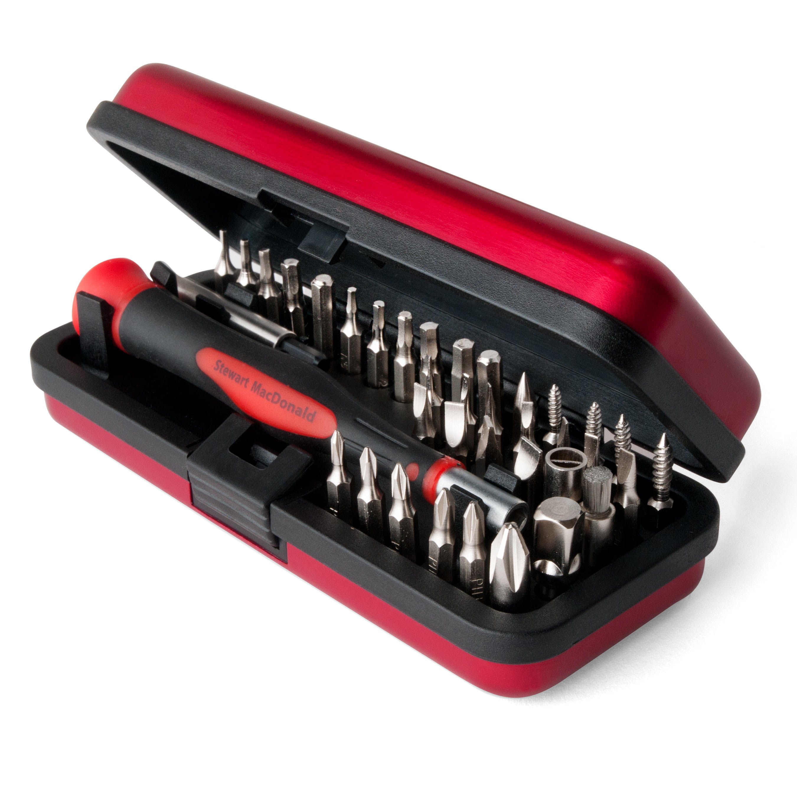
Pete: Yeah, apologies from my end, I got a little bit excited at the beginning here to get into this project. And we may have skimmed over the tool list, which you can find in the beginning of the instructions, the parts list and then the recommended tools and supplies. Join us next week, where I'll ask Tommy about the mysterious chopstick included in that tool list.
Rachel: All right.
Pete: Take care everyone, have a great night.

