Super Switch: Installation and Wiring
Installation and wiring instructions for the Super Switch.
This switch allows a level of flexibility and control that is not possible with traditional lever switches. These instructions are designed to give you an understanding of how the switch works how to develop your own custom ideas and set-ups. Coil cuts, series/parallel combinations, phase reversal and more can all be done.

Terminal assignment
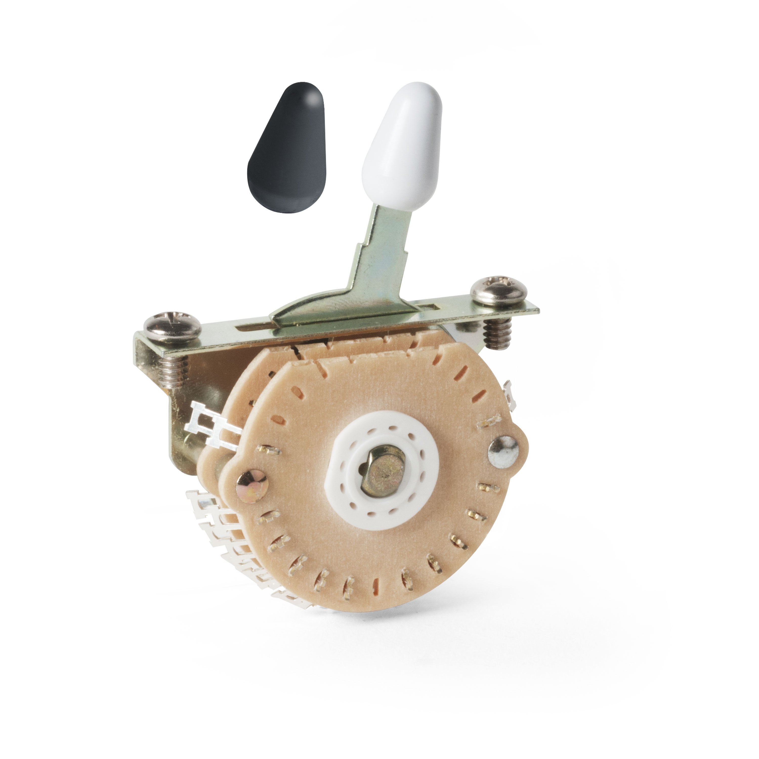
There are a total of 24 solder terminals (lugs) on this switch. The switch is divided into four separate circuits, or poles, and each pole has six lugs. Lug "0" is the "common" which is connected to other lugs depending on the lever's position. The five other terminals on each pole correspond to the five positions of the switch. Lug #1 = position 1, Lug #2 = position 2, etc.
Many lever switches use the commons as outputs for the switch, but with this switch this is not necessarily going to be the case. The commons of this switch can be used to connect pickups together in ways not possible with other switches. This is an important concept to understand when designing custom wiring for this switch.
Installation
The switch requires a 1/16" x 1-1/8" long slot and two 1/8" diameter mounting holes located 1-5/8" on center. The switch requires a minimum of 1-7/16" deep rout for adequate clearance for the wiring.
Soldering tips
When soldering to the switch, be careful not to overheat the terminal lugs. This could damage the switch, or cause other intermittent problems. We recommend pre-tinning all connections prior to soldering–for improved contact and better solder joints. Be sure to use small diameter rosin-core solder (DO NOT USE ACID CORE SOLDER!) and a 25-45 watt soldering pencil. Soldering guns are much too large for the small, delicate contacts of the components used in guitar electronics.
Humbucking pickups, phasing & magnetic polarities
A standard humbucker has two coils with opposite magnetic polarity, wound with the same number of turns and in the same direction. The coils are connected so that the current flows clockwise through one coil and counter clockwise through the other. This creates the hum canceling effect. The coils are connected in series for the most powerful sound but can be wired in parallel for a thinner, more single coil-like tone. The two coils can also be wired out of phase but the pickup will no longer be hum canceling when wired this way (see chart below).
Two single-coil pickups can be wired for hum-canceling operation, but only if they have opposite magnetic polarities. Use our #5127 Magnet Polarity Tester to determine your pickup's polarity and then use the Pickup Manufacturer's Specs chart to find the wind direction of the pickup. Refer to the chart above to get the desired phase relationship for wiring the switch and/or pickups.
If you're unsure of the manufacturer, or it's not listed in the chart, you'll have to experiment to find the proper leads to use for hot and ground. There is no easy way to determine the "start" and "finish" of a single-coil pickup without actually hearing it with another pickup. Wire up the two pickups and see if you get the desired effect:
Thin and nasal sounding = out-of-phase
Warm and full, but with a buzz = in-phase
Warm and full, and no buzz = in-phase, hum-canceling.
If the output sounds wrong, simply swap the two output wires of one of the two pickups.
Volume & tone potentiometer basics
It's up to the user to determine if controls will be used, and how many. Volume and tone controls use the same type of potentiometer but are wired differently to achieve the desired result.
Volume pots are wired in one of two ways. The traditional method (variation 1) is used most of the time. The second method (variation 2) is used if you have more than one volume control, and you don't want one pickup's volume control to effect another pickup's output.
In many cases, you may only be able to incorporate a single or master volume control. Often the output(s) from the pickups must be sent to the switch prior to controlling the volume. Depending upon how the switching circuit is designed, you may or may not be able to access the outputs of the pickups independently. Analyze your circuit, and see where you can insert the volume controls. Often, from a player's standpoint, the fewer controls on a guitar, the better.
Tone controls use a capacitor in conjunction with a variable resistor (pot) to bleed off treble frequencies. Typically, guitars use .020-.100 microfarad caps—experiment to see what value pot and cap gives you the desired effect with your pickups and amp. The higher the value of the capacitor, the more it affects the signal. This is subjective, there is no right or wrong, just what works best for the individual.
Continue to Page 2 for Pickup manufacturers and specs.
