Single-coil Pickup Kits
Assembly instructions for the single-coil pickup kit.
Smooth, and slightly round the edges of the fiber flatwork with very fine sandpaper to remove any roughness that might catch the thin wire during winding. Stratocaster®: The polepieces are in three lengths. The two longest pieces are for the D and G strings, and the shortest is for the B string. The remaining three are the same length, and they are for the E, A, E strings. Telecaster® bridge: The polepieces are in two lengths. The two longest pieces are for the D and G strings, and the remaining four are the same length, and they are for the E, A, B, and E strings. Tele neck: The polepieces are the same length.
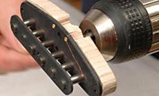
To hold the polepieces upright while installing them, make a small jig with a hole just larger than the polepieces. Drill a 19/64" hole through a short length of hardwood or acrylic, 1/4" thick x 3/8" wide. An accurately drilled hole will hold the polepieces squarely and keep your fingers out of the way when pressing or tapping the pieces into the flatwork.
Option 1: Using a small hammer (one with a plastic or brass head is the most gentle), firmly tap in the magnets while the flatwork rests on a support block placed on a very solid, flat surface. Option 2: Press the polepieces into the flatwork using a drill press. Close the jaws in the drill press chuck and use the flat underside of the chuck as an overhead press.
The thickness of the eyelets in the bottom flatwork will keep it from laying flush to the work surface, so let them hang over the edge of a support block during installation. For Strat and Tele bridge pickups, install the shorter polepieces first and the longer pair last, so that you're not trying to hammer a shorter piece while hitting a taller one that's already installed.
Once they're installed, make sure the polepieces are square to the flatwork and parallel with each other. If they're not, or if the flatwork is warping, manipulate the pieces until the poles are squarely seated and the fiber pieces are flat.
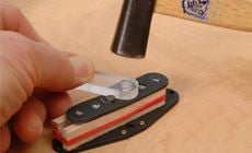
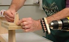
Pieces of hardwood placed on each side of the polepieces will serve as spacers to make sure the top flatwork is at the right height, leaving a gap of 7/16"-15/32" for the wire. Cut two pieces measuring 2-1/2" x 7/16" x 1/8". For Tele pickups, cut two pieces measuring 2-1/2" x 15/32" x 1/8". Use a rubber band to hold them in place beside the polepieces (photo). The holes in the top piece are tighter than the bottom holes. The fiber will press over the magnets, but not as easily—the sharp edges of the magnets will punch out a small amount of fiber as the top flatwork is pressed on. Option 1: Tap the top piece on with your hammer, using the polepiece-holder you made as a caul to protect the flatwork as shown in the photo. Option 2: The drill press can be used again to provide downward pressure. A small socket wrench or similar shape held in the drill press chuck can provide a caul to press the flatwork onto the polepieces.
Start on the two tallest polepieces first (D-G). Alternate between them, applying pressure (or tapping) until the flatwork is started over both pieces. Again, the flatwork may warp out of shape slightly—keep this to a minimum by frequently alternating, pressing or tapping each hole equally.
As the D-G poles start to come through the top of the flatwork, your polepiece-holder will become helpful in tapping the flatwork down.
When all the magnets have started through the holes, be sure to have your two wooden spacers in place. The top flatwork is installed when it is flush against these two spacers. The spacers should be snug when you're finished, but will pull out with little trouble.
Fender used both 42AWG (American Wire Gauge) and 43AWG coil wire for their pickups. Stratocaster pickups were all wound with 42AWG, while Tele neck pickups were all wound with 43AWG. The very earliest Broadcaster and Telecaster bridge pickups used 43AWG, but switched to 42AWG sometime in the early fifties.
There are lots of ways to wind a pickup. Virtually anything that spins with a controllable speed could be rigged to do the job (you can see a winder made of Lego's on YouTube!). But it's easier and more accurate to use a pickup winder with digital counter and speed control.
The number of winds, the coil wire tension, and the way in which you build up the layers of wire all affect the tone of your pickup. Don't make the winds too tight, or you could cause the pickup to deform from the pressure. If your winds are too loose, you could have problems with excessive feedback. Pickups from the '50s and early '60s were wound clockwise (when viewed from the top of the pickup) with approximately 8000 turns of wire. If you don't have a counter, you can start by looking at another pickup and visually matching the size of its coil. Reverse wound/reverse polarity: Several vintage Fender models (Jazzmaster, Duo-Sonic, Jazz Bass to name a few) shipped with reverse wound/reverse polarity (RW/RP) pickups to allow for hum canceling positions when two or more pickups are combined. Strats and Teles did not have this feature when they were released in the 50's but modern versions have adopted it for regular production.
For RW/RP pickups on a Tele the bridge pickup is wound clockwise (when viewed from the top of the pickup) with the magnets charged South up. The neck is wound counterclockwise with the magnets charged North up. This will give you a hum canceling connection in the middle position when both pickups are combined.
For a Strat, wind the neck and bridge coils clockwise with the magnets charged south up. Wind the middle pickup counterclockwise with the magnets charged North up. This will give you hum canceling connections in the 2 & 4 positions on a 5 way switch. Overwound, underwound: You can also tweak the number of windings for a custom sound. For example, winding a coil 5% under spec can give you a sound that is brighter while overwinding by the same amount can give you a warmer sound with less top end. Attach the pickup to your winder. Depending on the winder, this might mean using double-stick tape (carpet installation tape is strong) or another fastener. Carefully center the pickup square to the winding shaft. If your winder has a flat pickup mounting plate, the metal eyelets on the underside of the pickup will keep the flatwork from sitting flat on the surface. Multiple layers of double-stick tape can shim it up while holding it, or you may want to file a groove into the mounting plate to accommodate the thickness of the eyelets. You'll be moving the wire back and forth as it feeds onto the coil, so set the "traverse limiter" on your winder so the coil wire stops about .020" from the flatwork on both sides. This helps prevent the windings from deforming and also helps keep the wire from hanging up on the eyelets.
If you have a winder with a counter, set it to zero. Start the first 6-10 wraps turning the drill winder by hand, to be sure that the coil wire won't be pulled off the bobbin when you start the winding.
Coil wire is thin and easy to break! Control your winding pressure, and the drag on the wire, by folding a piece of felt over the wire as you hold it. Talcum powder on your hand is another way to keep a light hold on the wire without sticking. If you break the wire, you can choose to start over, or you can sand the insulation off the wire ends and solder them back together.
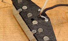
When you're done winding, cut the coil wire, leave enough to reach the eyelets with at least 2" to spare. Sand the coating from the end of the wire and wrap it through the treble-side eyelet. The start and finish ends leading to the eyelets should be snug and flat against the bottom flatwork.
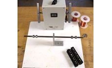
This crafty example demonstrates that you can wind a pickup with very simple gear. It's economical, although it has no way to count the number of winds.
Clamp an electric hand drill to a workbench. The speed control is simply a second clamp which is tightened onto the drill trigger: screwing it down tighter presses the trigger and speeds up the drill.
We fashioned a mounting plate in the shape of the pickup (with a recess for the eyelets), and mounted that onto a metal shaft that's held in the drill chuck. Whatever your method, see that the pickup is spinning true and straight.
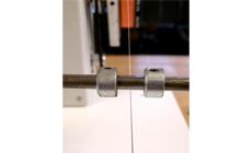
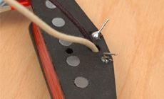
You'll be moving the wire back and forth as it feeds onto the coil, and you'll want to create a "traverse limiter" to keep it between the two flatwork pieces (this is a polished metal rod with adjustable right and left limiters). For this simple winder, the limiter is a hole drilled in a piece of wood that pivots right and left. The hole must be sanded very smooth. Strat pickups: From the underside of the pickup, feed the black and white hookup wires through the center hole between the eyelets. The black wire will be soldered to the start of the coil wire and the white is for the finish. Expose (push-back the covering) approximately 3/16" of the lead wires and carefully feed them down into the eyelets on the bottom of the pickup, solder each wire to its eyelet and coil wire. Tele bridge pickups: From the underside of the pickup, feed the black and white hookup wires through the center hole between the eyelets. Expose (push-back the covering) 3/16" of the white wire and 1/2" of the black wire (you may need to use wire stripers rather than simply pushing back the black wire's covering to expose 1/2" or wire), then carefully feed them down into the eyelets on the bottom of the pickup. Solder each wire to its eyelet and coil wire—the black wire will be soldered to the start of the coil wire and the white is for the finish. The extra length of exposed black should extend below the pickup and is used to solder to the bridge pickup's baseplate. Once the leads are soldered to the eyelets, solder the extra length of black wire to the bottom of the copper plate.
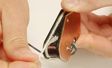
Traditionally the copper-plated steel plate isn't attached to the bottom flatwork other than by the magnets and in the pickup potting process where the wax will hold it in place. To reduce the chance of microphonic feedback, the plate can be glued to the bottom flatwork using silicone caulking—run a small bead of caulk along the bottom of the polepieces and clamp the plate to the pickup. After the caulk cures, the pickup is ready to be wrapped with string. The white string is wrapped around the coil to protect the delicate windings. You may want to test the pickup with your volt/ohm meter before wrapping the pickup (see "Test the DC resistance"). To wrap the pickup, lay about 1/2" of the end of the string on the side of the coil. Carefully wind the string around the coil so that the windings completely cover the coil wire. The end of the string can be tucked beside the last few windings of string and the flatwork. This will hold the string in place until the pickup gets potted. Tele neck pickups: From the underside of the pickup, feed the black and white hookup wires through the center hole between the eyelets. Expose (push-back the covering) 3/16" of the white wire and 1/2" of the black wire (you may need to use wire strippers rather than simply pushing back the black wire's covering to expose 1/2" of wire), then carefully feed them down into the eyelets on the bottom of the pickup. Solder each wire to its eyelet and coil wire—the black wire will be soldered to the start of the coil wire and the white is for the finish. The extra length of exposed black should extend below the pickup and is used to solder to the neck pickup's cover. You may wish to test your pickup prior to soldering the cover in place (see "Test the DC resistance"). To install the cover, first use a file or sandpaper to remove the plating on the center tab—this will allow it to take the solder better. Carefully slide the cover over the top of the pickup, making sure that the center tab slides in the hole where the two lead wires come up through the bottom flatwork. Press the cover down flush with the flatwork–be careful not to damage the two fine coil wires leading from the eyelets to the coil. With the cover in place, use a flat tool such as a blade screwdriver to bend the two outside tabs under the flatwork. The center tab isn't bent down, instead, solder the extra length of black lead wire to the center tab.
Test with a volt/ohm meter set to the 20K range. A Strat pickup should be about 5.75K-6.75K. If you get an open circuit: are your connections to the coil wire good? Did you solder a break inside the coil which is now causing a short?
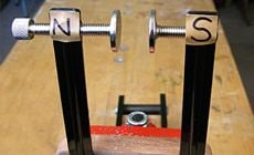
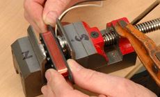
The polepieces are now ready to be magnetized by passing them between two strong magnets held apart with just enough room to pass the pickup between.
Option 1: Make a simple fixture using our 5" soundhole clamp. Remove the feet with a screwdriver and attach two of our 1" diameter Guitar Repair Magnets with #20 Super Glue. Orient the magnets so that they pull toward each other, and adjust the magnets so they are 1" apart. Identify and mark the north/south polarity for reference. Fender Strat pickups were always "north up" until 1960 when they became south up. Use our Magnet Polarity Tester to determine a magnet's polarity. Option 2: For an adjustable-width magnetizing fixture, our Nut and Saddle Vise #1816 works well. Since the jaws are steel, the Guitar Repair Magnets hold themselves in place without glue. This lets you adjust for different pickups and different proximity by simply opening and closing the vise.
The Guitar Repair Magnets will charge the magnets to their full capacity of 20-25 Gauss. Several passes through the magnets does the job; move the pickup as slowly as you can while keeping it free of the magnets. To determine a magnet's strength, we recommend the analog Model 25 Magnetometer (50-0-50 gauss range) available from the R.B. Annis Company. It works well and is reasonably priced.
Potting a pickup (dipping it in melted wax or other material) helps eliminate unwanted microphonics and feedback. Although early Fender pickups weren't potted, potting's generally a good idea.
Wax is a traditional pickup potting material that works for most pickups, it’s non-toxic, easy to deal with, cheap, and you can undo it if something goes wrong.
Danger: If the wax is too hot you can warp or melt plastic bobbins. If the wax is way too hot you have a potential fire on your hands! Make sure that the wax never smokes—that’s an indicator that it’s getting too hot. Never try heating your wax on the kitchen stove or in a microwave oven because hot paraffin, and especially paraffin vapors, can ignite. It’s best to wax pot outdoors until you have your methods refined and have eliminated any fire hazards.
Stewart-MacDonald’s Hot Glue Pot (#0668) has a thermostat designed to heat hide glue to about 145°. Keep the pot at least 2/3 or 3/4 full. It can operate with less liquid, but the wax may get too hot.
Application: After a pickup has been wound, and the output wires are attached and assembled, suspend the pickup in canning paraffin mixed with 20% beeswax, heated to 145-150 degrees Fahrenheit. After ten or fifteen minutes all of the bubbles should have risen out of the pickup, and all of the voids within the pickup should be filled with a coating of wax.
Pull the pickup out of the wax and suspend it over the wax pot letting the excess wax drip back into the pot. Then lay the pickup on a paper towel and allow it to cool to touch. Carefully remove any excess with a paper towel before the pickup completely cools to room temperature.
PREPARE THE FLATWORK
INSTALL THE POLEPIECES


INSTALL THE TOP FLATWORK
CHOOSE YOUR WIRE
WIND THE COIL


HOMEMADE HAND DRILL PICKUP WINDER
(single-coil pickup shown in our photos)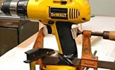
SOLDERING THE LEAD WIRES
TEST THE DC RESISTANCE
CHARGE THE MAGNETS
PICKUP POTTING


