MacRostie Binding Trimmer Instructions
Assembly and operation instructions for the MacRostie Binding Trimmer.
Select the router/laminate trimmer you wish to use and make sure it recesses into the 6" round recess hole on the underside of the base. If not you may need to rout or chisel a little more plywood to allow the base to fit. Most standard routers/laminate trimmers will fit into this recess. Remove the "secondary" base plate (usually black, easy-skid plastic) by removing the 3 or 4 screws that attach it. If you're not using this router, use the following instructions to mount your router: 1. Install a 1/2" bit into the router collet. 2. Insert the bit into the hole in the center of the recess on the plywood. This will center the router so that the bit will be in the correct location for trimming binding. 3. With the router in position mark the location of the base holes using a pencil through them (mechanical is best). 4. Remove the router and carefully drill the holes. Countersink the holes from the upper side. If regular headed screws are provided with your router, you can either counter-bore for them or visit your local hardware store and replace them with like threaded "flat head" screws. 5. Put the router back in the recessed pocket and install the screws that hold the router. Make sure that the heads of the screws are recessed safely below the surface of the plywood. 6. With the bit below the plywood table, turn the router on and slowly raise the bit through the table. This will make sure that there is some clearance between the bit and the hole in the plywood. 1. Holes have been drilled for the (4) threaded T-nuts that are provided. These need to be pressed or hammered into the holes through the underside of the plywood. The nut flange should seat into the hole's counterbore. 2. The longer thumbscrew and the spacer bushing are used for the curved slot in the Binding Trimmer, and this will lock the adjusting feature. It is best to install this screw first. Start threading the screw but don't tighten it. 3. Line the countersunk hole at the other end of the Trimmer with the single hole to the right. Install the Allen head flat head screw into that T-nut. Tighten both at the same time (no need to overtighten). 4. Fasten the two short thumbscrews through the slots of the indicator plate and into the two holes in the middle rear of the plywood plate. The slots in the indicator base will allow full adjustment of the indicator to read anywhere the Binding Trimmer can be positioned. The side tensioning is controlled by using various spring holes to increase or decrease tension on the clear keeper holding the binding. The brass knurled tension knob on the top of the hold-down is used to control downward tension on the binding strip. Two small thumbscrews at the front of the trimmer fence are centering knobs and adjust where the hold-down foot rides on the strip being trimmed. It is best to adjust the hold-down foot to ride in the middle of the strip so that even hold-down pressure is achieved. 1. Run a strip of binding material through the trimmer prior to using it with the router. 2. Now raise the router bit so the top of it will be a little bit above the top edge of the binding. Loosen the thumbscrew that is in the curved slot and swing the trimmer until the router bit almost touches the edge of the binding. With the binding out of the trimmer, turn the router on and pull the binding into the trimmer. It probably won't cut, so move the trimmer about .010" closer and try again. 3. Once the router starts cutting the binding material, measure it and set the bezel on the indicator to the measurement you get. Only worry about the large dial reading and use the small (red) numbers. This will allow for direct adjustment of the jig. Once set, the binding width should measure what the dial reads. When trimming binding, take it in small increments and don't try and reduce the width all at one time. 4. Binding that is not too tall or not too thin can be thicknessed on this tool. As binding gets thin and the cut gets wider (tall binding) the stiffness-to-cutter pressure ratio will cause the binding to vibrate and chatter, thus causing a poor cut. 5. An acrylic cutter guard is installed to prevent accidental hand contact with the rotating cutter. Be sure to use this tool safely, which includes not removing the guard, and wear hearing protection, safety glasses, and respiratory/dust protection.ASSEMBLY
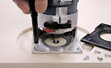
Mount a router in the plywood base.
Our base is drilled for use with the Bosch Colt Router.
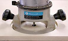
Next, mount the Binding Trimmer and Indicator Plate.

OPERATION

Be safe when using rotary tools. Wear hearing protection, safety glasses, a dust mask, and always use proper ventilation.
